(0)
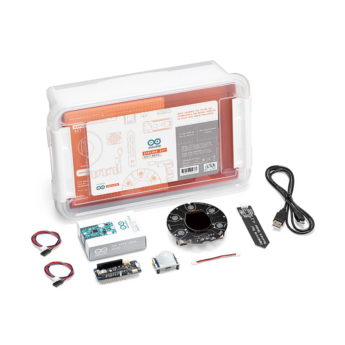
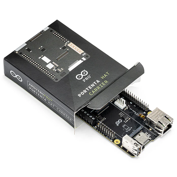
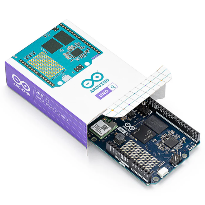
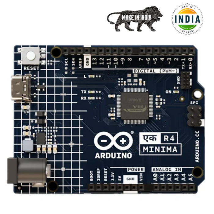
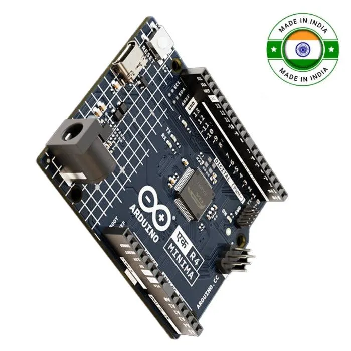
Official Arduino UNO Q SBC ABX00162
The Official Arduino UNO Q is a versatile single board computer designed for makers, developers, and innovators.
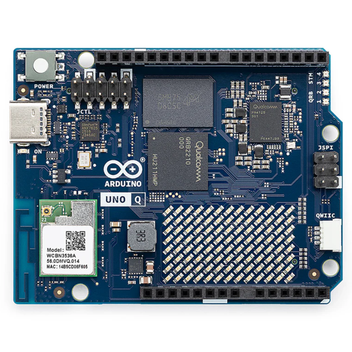
Its hybrid architecture combines a Linux® Debian-capable Qualcomm® Dragonwing™ QRB2210 microprocessor with a real-time STM32U585 microcontroller, giving you the flexibility to run AI-powered vision and sound applications while maintaining real-time control.
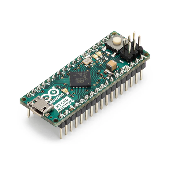
Fully compatible with the Arduino UNO ecosystem, it supports classic shields, Modulino® nodes, and third-party modules via the Qwiic connector.
With seamless software integration through Arduino IDE, Arduino Cloud, or Python® on Linux®, plus pre-built examples and AI models available in Arduino App Lab, the UNO Q makes building advanced projects intuitive and powerful.
Dual-Core Processing Power
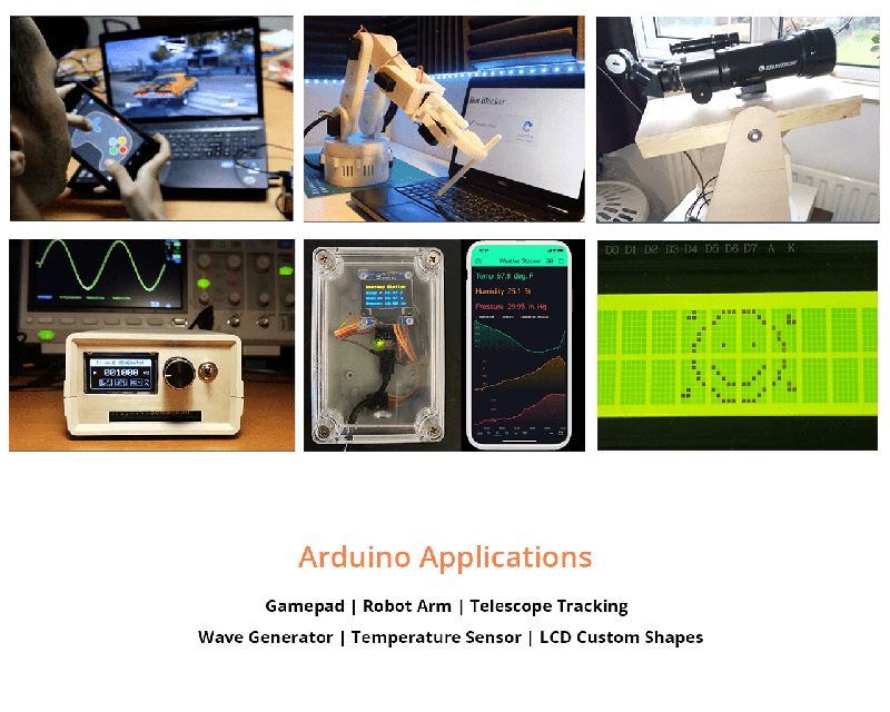
Robotics and Embedded Application
Hands-On Development and Programming
The Illuminated Command Center
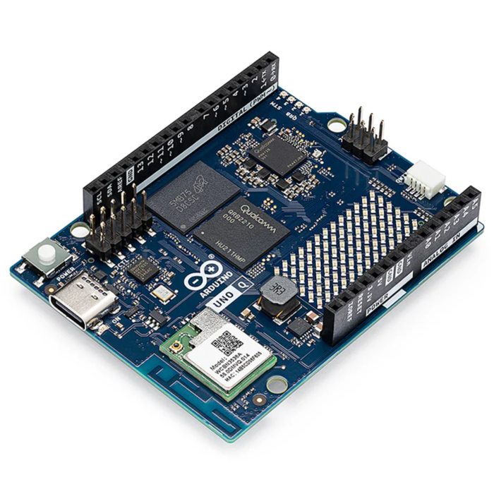
Powered by Qualcomm Dragonwing QRB2210
Your UNO Q is a compact, cost-effective platform with advanced features such as machine vision, owing to the Dragonwing QRB2210's integrated AI and GPU acceleration, quad-core 2.0 GHz CPU, Adreno GPU, 2x ISP, and support for camera, display, and audio.
Features:
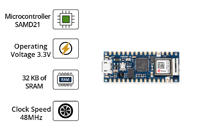
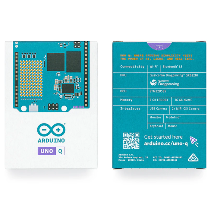
Microprocessor:
Qualcomm® Dragonwing™ QRB2210.
Microcontroller:
Real-time and low-power STM32U585 MCU
RAM:
2 GB LPDDR4.
Storage:
16 GB eMMC built-in (no SD card needed).
Connectivity:
options include dual-band Wi-Fi® 5 (2.4/5 GHz) and Bluetooth® 5.1
High-speed headers:
Power advanced peripherals (vision, audio, display)
Classic UNO headers:
Mount shields to increase capabilities.
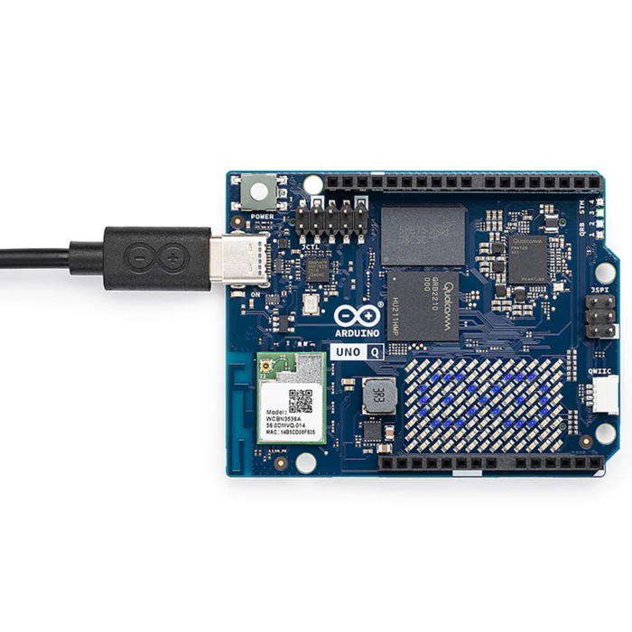
LED matrix:
(8 x 13) for visual creation and feedback.
USB-C Connector:
Power delivery, video output, or connecting a keyboard, mouse, USB microphones, or USB cameras via dongle
Qwiic Connector:
Modulino® nodes allow for easy expansion without the need for soldering.
What is Arduino App Lab?
Unified Developer Experience
App Lab is a brand-new comprehensive development environment that unifies the journey from Linux® to real-time OS.
Preloaded on the UNO Q, App Lab combines Arduino Sketches, Python® scripts, and containerized AI models to create fully integrated applications that can be administered from a single interface.
Ready-to-use Apps and Bricks
Get started quickly with Arduino Apps, self-contained examples that include everything you need. Add plug-and-play capabilities to your projects using pre-built Bricks to help you push your ideas even further.
Pre-loaded AI models
With pre-loaded AI models in Arduino App Lab, you can use real-world data for a variety of tasks, including object/human detection, anomaly detection, image categorization, sound recognition, and keyword spotting.
₹5173.13
Backorder Available
₹9798.60
Incl. GST (No Hidden Charges)