

Sort by
L86-M33 GPS GNSS Breakout Mod…
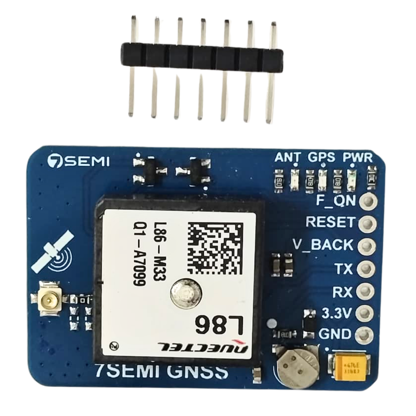
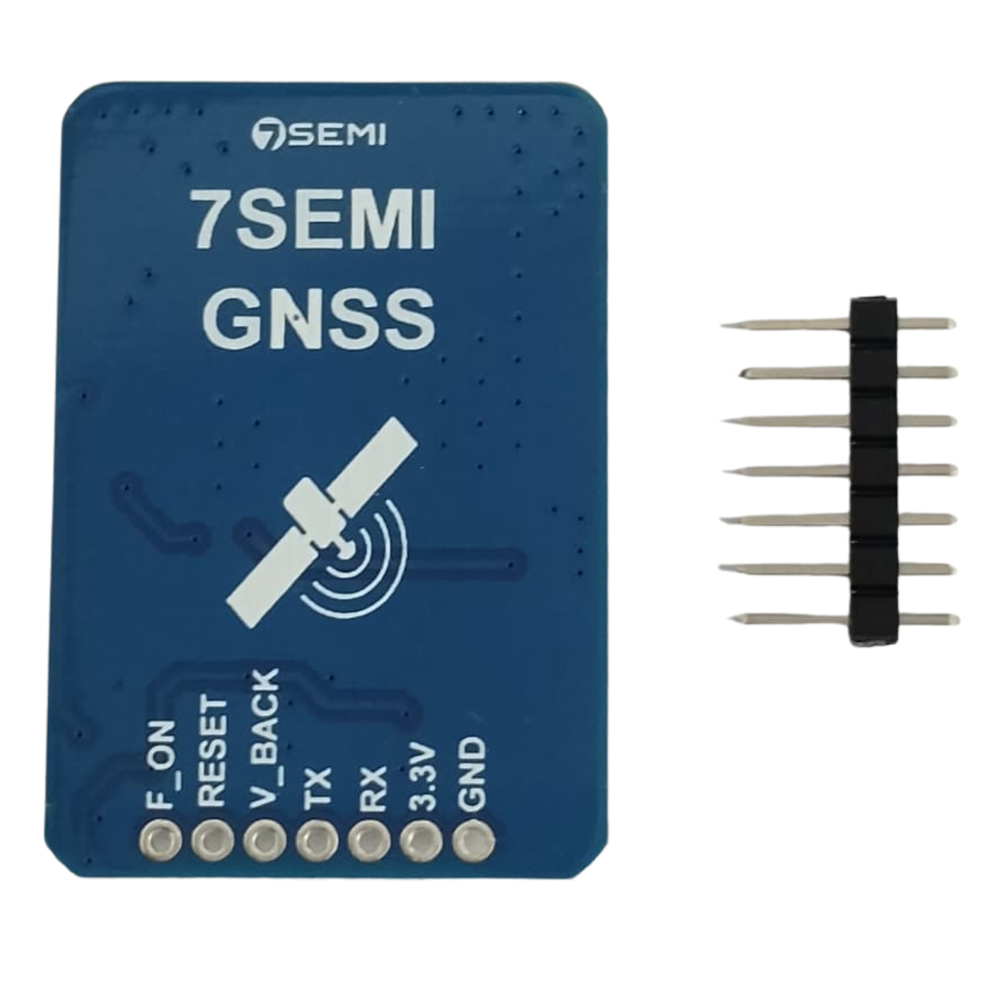
L86-M33 GPS GNSS Breakout Module -7Semi
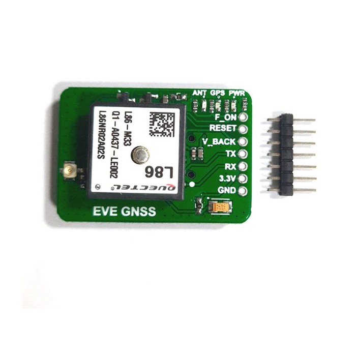
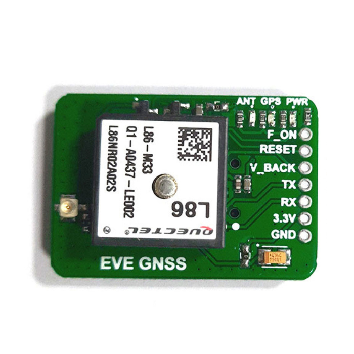
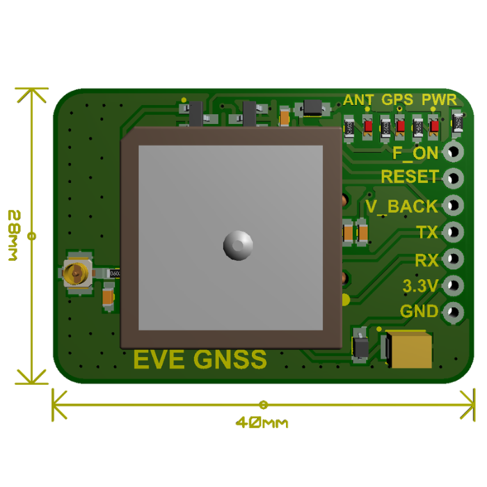
The L86-M33 GPS GNSS Breakout Module by 7Semi is an advanced and compact positioning solution designed for precise and reliable location tracking across a wide range of applications.
Featuring Quectel’s ultra-compact L86 GNSS module with an integrated patch antenna and an option for an external active antenna, this breakout board leverages the power-efficient MediaTek MT3333 chip.
It operates at 3.3V and communicates via UART, making it highly compatible with various microcontrollers. The module’s AGPS EASY orbit prediction technology enables fast and low-power satellite acquisition, even under weak indoor signals, while the AlwaysLocate technology intelligently adjusts positioning time to minimize power consumption without compromising accuracy.
Additionally, the L86 supports automatic antenna switching with plug-in detection and built-in short-circuit protection, ensuring uninterrupted GNSS reception. Perfect for professional and hobbyist use alike, this module is well-suited for drones, robotics, automotive tracking, industrial devices, and personal navigation systems.
Features:
The board features a 3.3V power supply and a UART communication port.
Support several satellite systems, including GPS, GLONASS, Galileo, and QZSS.
Internal patch antenna is 18.4 x 18.4 x 4.0 mm.
Support automated switching between internal and external antennas.
Enable short circuit protection and antenna detection.
Built-in low-noise amplifier improves receiving sensitivity.
Support self-assisted AGPS (EASYTM technology, no external memory required).
Very low current consumption. 26mA @tracking mode.
Several power-saving modes: standby mode, backup mode, periodic mode, and AlwaysLocate mode.
LOCUS technology enables automatic log information recording and storage.
High sensitivity: -167dBm @ tracking mode and -149dBm @ acquisition mode.
Number of channels: 99 capture channels and 33 tracking channels
Support Balloon mode, setting altitude up to 80 kilometers.
Support DGPS and SBAS (WAAS/EGNOS/MSAS/GAGAN).
Multi-frequency active interference cancellation technology improves anti-interference ability.
Time service offers PPS and NMEA synchronization functions.
Support Quectel's independently created SDK commands.
₹940.80
MRP. ₹1659.00
Incl. GST (No Hidden Charges)
Incl. GST (No Hidden Charges)
L86-M33 GPS GNSS Breakout Module -7Semi
L86-M33 GPS GNSS Breakout Module -7Semi The L86-M33 GPS GNSS Breakout Module by 7Semi is an advanced and compact positioning solution designed for precise and reliable location tracking across a …
As low as
₹940.80
₹940.80
MRP. ₹1659.00
Incl. GST (No Hidden Charges)
L89HA Multi-GNSS Breakout Mod…
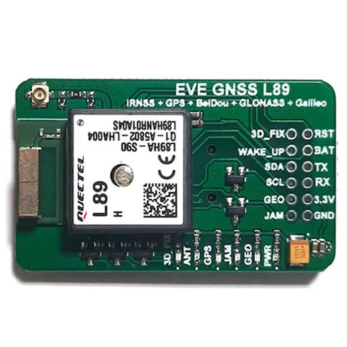
L89HA Multi-GNSS Breakout Module for GPS, IRNSS, GLONASS, BeiDou, Galileo & QZSS - 7Semi
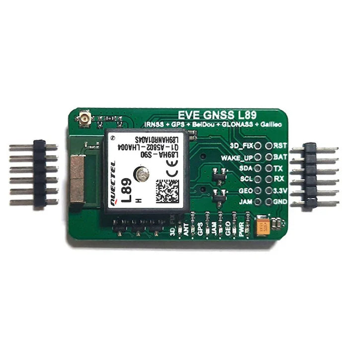
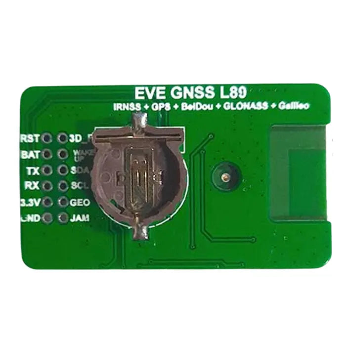
The L89HA Multi-GNSS Breakout Module is a compact and high-precision navigation solution based on the Quectel L89 module. It supports GPS, IRNSS, GLONASS, BeiDou, Galileo, and QZSS, enabling accurate and fast positioning with concurrent L1 and L5 band reception.
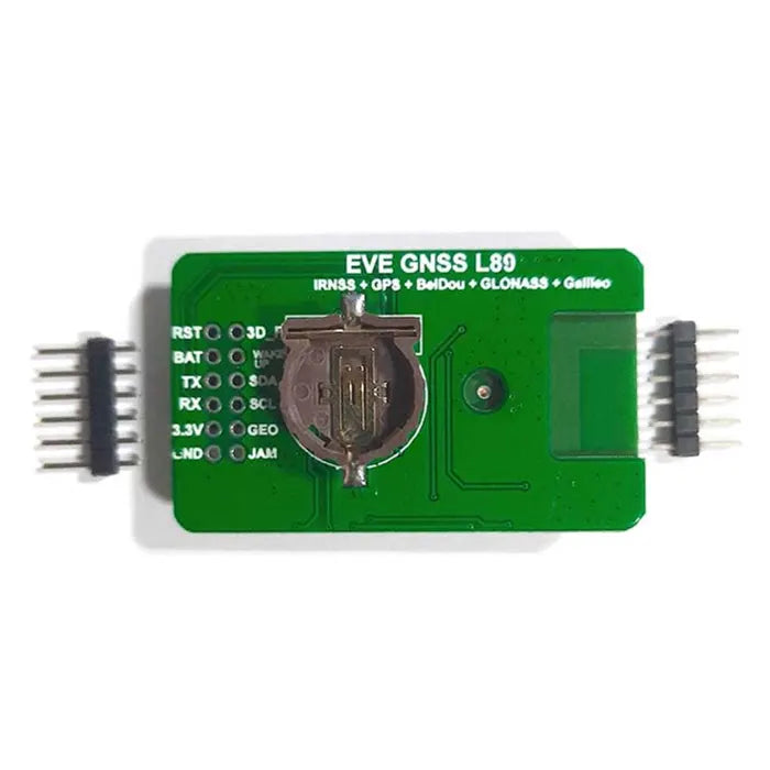
Powered by 3.3v, the L89 GNSS module offers I2C and UART interfaces for easy integration with various microcontrollers. It also features dual embedded antennas and a backup battery pin (BAT) for uninterrupted operation.
This L89 module is ideal for drones, wearables, smartphones, IoT devices, and any compact system requiring reliable GNSS tracking, geofencing, or timing. With high sensitivity and multi-constellation support, it ensures strong performance even in challenging environments.
L89 Breakout Dimensions
Features
Operates on a 3.3V power supply
Supports both I2C and UART communication interfaces
Compatible with IRNSS L5 band for enhanced regional accuracy
Built-in patch antenna and chip antenna for compact integration
Multi-GNSS support: GPS, IRNSS, GLONASS, BeiDou, Galileo, and QZSS
Supports DGPS and SBAS (WAAS, EGNOS, MSAS, GAGAN) for improved positioning accuracy
Integrated Low Noise Amplifiers (LNAs) for better signal sensitivity
Excellent anti-jamming performance with multi-tone active interference cancellation
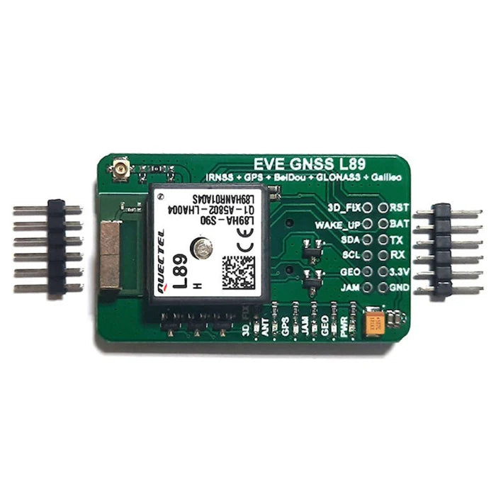
L89 Breakout Arduino Connection
How to Enable IRNSS (NavIC) on the L89 GNSS Module
Follow the steps below to enable IRNSS (NavIC) on the L89 module:
Connect Hardware
Use a USB to Serial converter to connect the L89 module to your PC.
Open QNavigator
Launch QNavigator software and open the serial port connected to the module.
Enter AT Command
To enable IRNSS, send the following AT command:
PSTMSETCONSTMASK,1024
Use an External Active Antenna
Ensure you're using an external active antenna and position it under an open sky for best reception.
Access Command Manual
For more details, download the L89 AT command manual from the resources section.
₹1196.83
MRP. ₹2056.60
Incl. GST (No Hidden Charges)
Incl. GST (No Hidden Charges)


L89HA Multi-GNSS Breakout Module for GPS, IRNSS, GLONASS, BeiDou, Galileo & QZSS - 7Semi
L89HA Multi-GNSS Breakout Module for GPS, IRNSS, GLONASS, BeiDou, Galileo & QZSS - 7Semi The L89HA Multi-GNSS Breakout Module is a compact and high-precision navigation solution based on the Quectel …
As low as
₹1196.83
₹1196.83
MRP. ₹2056.60
Incl. GST (No Hidden Charges)
L9110S H Bridge Stepper Motor…
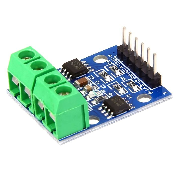
L9110S H Bridge Stepper Motor Dual DC Driver Controller Module For Arduino
The L9110S dual channel h-bridge motor driver module is a compact board that can be used to drive small robots. This module is based on L9110 Motor Driver IC. This module has two independent
motor driver
chips which can each drive up to 800mA of continuous current. The boards can be operated from 2.5 volts to 12 Volts enabling this module to be used with both 3.3 Volts and 5 Volts microcontrollers. A set of female header pins and
jumper wires
are used to connect this module to a microcontroller like
Arduino
. The motors are attached via two sets of screw terminals.
A PWM Pulse Width Modulation signal is used to control the speed of a motor and a digital output is used to change its direction. This module can also be used to drive a single four-line two-phase stepper motor. Four holes make this board easy to mount onto your robot or other projects.
This dual-motor driver comes in a compact form factor and it is ideal for use in small robots.
The actual direction of “forward” and “reverse” depends on how the motors are mounted and wired. You can always change the direction of a motor by reversing its wiring.
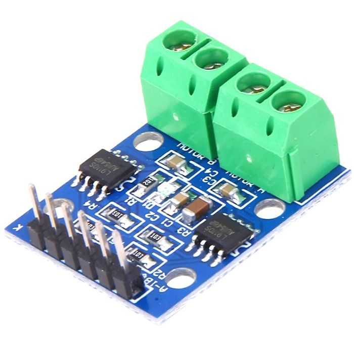
The HG7881 (L9110) Dual Channel Motor Driver Module uses two of these motor driver chips. Each driver chip is intended to drive one motor, so having two means that this module can control two motors independently. Each motor channel uses the same truth table as above. Each set of screw terminals is used to connect a motor. Refer to the table below for pin header connections.
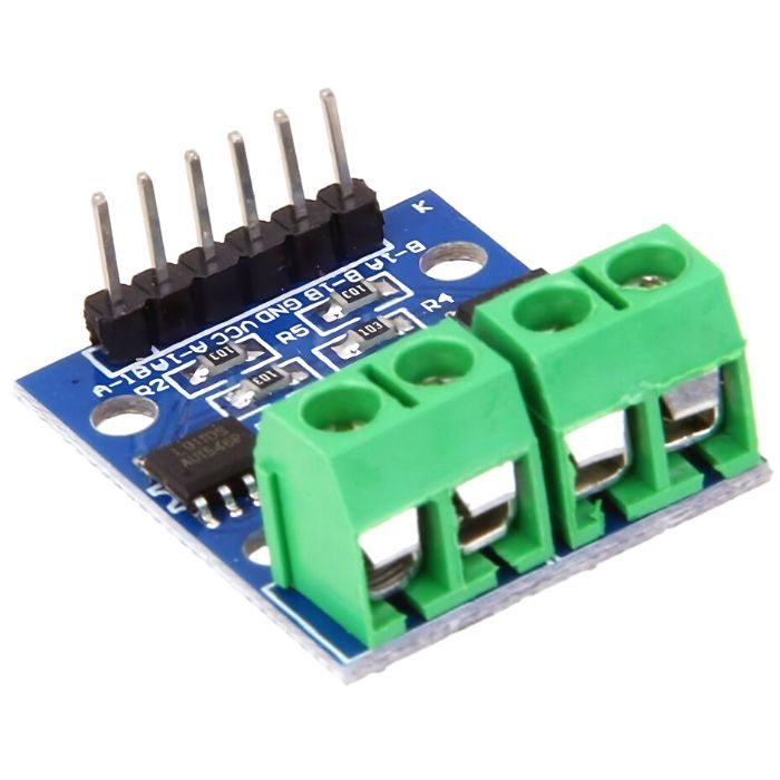
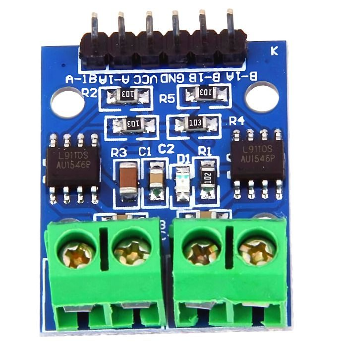
Pin diagram of L9110S H Bridge Stepper Motor Dual DC Driver Controller Module:
L9110S DC Stepper Motor Driver Board Pin Diagram
Module Interfaces:
6P black bent pin description:
1 VCC external voltage 2.5V-12V
2 GND External GND
3 AIA external microcontroller IO port
4 AIB external microcontroller IO port
5 BIA external microcontroller IO port
6 BIB external microcontroller IO port
4P green terminal:
1 OA1 OB1 contact DC 2-pin, non-directional
2 OA2 OB2 contact DC 2-pin, non-directional
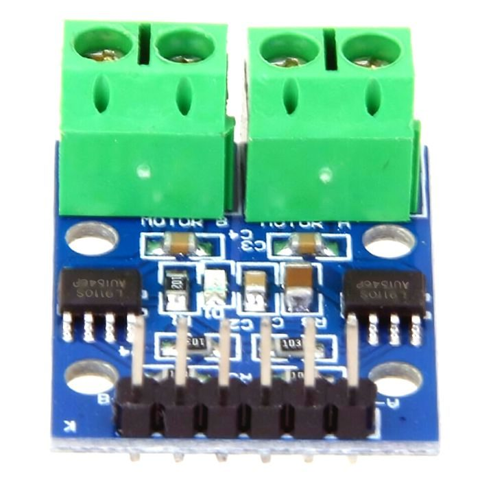
Use:
ON VCC, GND module power indicator light
AIA input high, AIB input low, [OA1 OB1] motor is transferred;
AIA input low, AIB input high, [OA1 OB1] motor reversal;
BIA input high, BIB input low, [OA2 OB2] motor is transferred;
BIA input low, BIB input high,] [OA2 OB2] motor reversal
Features:
L9110S-chip motor drive
Small-sized, suitable for assembly
This can drive two DC motors or a 4-wire 2-phase stepping motor
This is provided with fixed mounting holes
₹46.74
MRP. ₹103.60
Incl. GST (No Hidden Charges)
Incl. GST (No Hidden Charges)
L9110S H Bridge Stepper Motor Dual DC Driver Controller Module For Arduino
L9110S H Bridge Stepper Motor Dual DC Driver Controller Module For Arduino The L9110S dual channel h-bridge motor driver module is a compact board that can be used to drive …
As low as
₹46.74
₹46.74
MRP. ₹103.60
Incl. GST (No Hidden Charges)
Laser Module
Laser Module
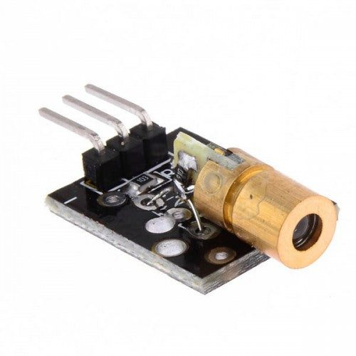
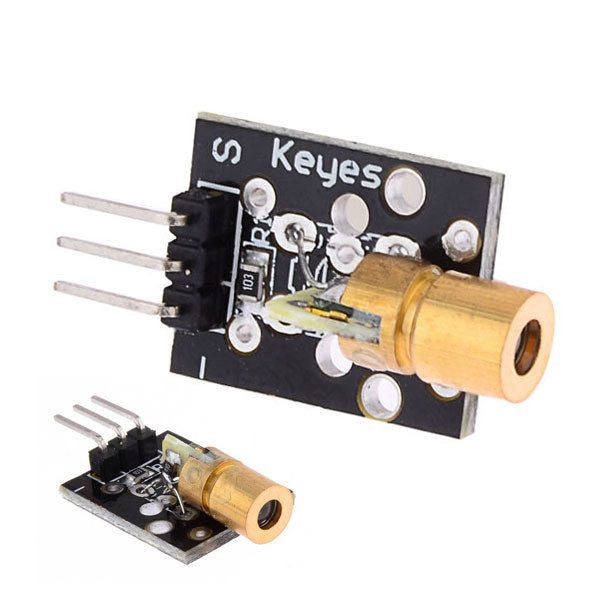
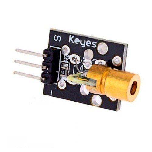
A laser module is a device that produces a highly focused beam of light, usually in the visible or infrared range. A laser diode, a power supply, and a focusing lens are typical components of a laser module. A laser diode is a semiconductor device that emits a light beam when current is supplied through it.
The Laser
Sensor Module
is composed of a light-emitting tube, condenser lens, and adjustable copper sleeve and it is assembled when delivered, the focal length of the lens is adjusted glued by strong glue stick, which can work directly after connecting to a 5V DC power supply.
Pay attention to the laser cell to prevent from being burnt or battery explosion due to a short circuit when removing the battery.
The Laser Module is an advanced, easy to use tool that offers users a wide range of applications and functions. This high-tech device makes it possible for the user to control lighting levels and colours in their interior or exterior space by converting electrical signals into soundwaves which can be manipulated accordingly.
The module has been designed using robust components backed with reliable technology specifically made for precise performance even under challenging conditions like low-temperature environments or dusty locations making them ideal for industrial settings. Moreover, its compact size allows users to carry it around easily wherever they go providing precision-regulated power output every time without any downtime worries ensuring complete reliability at all times regardless of whatever environment you might find yourself operating in!
check out :
650nm 6mm 5V DC Mini Laser Dot Diode Module
Pinout:
1 – GND
2 – 5V
3 – S (Control: HIGH = Laser on)
Applications:
Laser test tools.
Concentricity positioning.
Medical equipment positioning.
Production of signal equipment.
Use for DIY or robots.
All kinds of level meters.
Laser projector.
Laser toys, etc.
Package Include:
1 x Laser Module
₹30.48
MRP. ₹61.60
Incl. GST (No Hidden Charges)
Incl. GST (No Hidden Charges)
Laser Module
Laser Module A laser module is a device that produces a highly focused beam of light, usually in the visible or infrared range. A laser diode, a power supply, and …
As low as
₹30.48
₹30.48
MRP. ₹61.60
Incl. GST (No Hidden Charges)
Laser Receiver Module
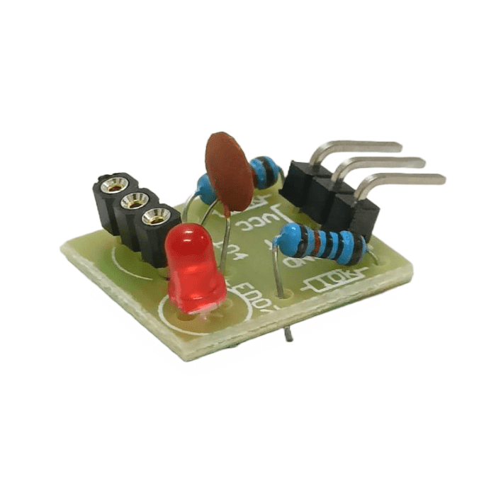
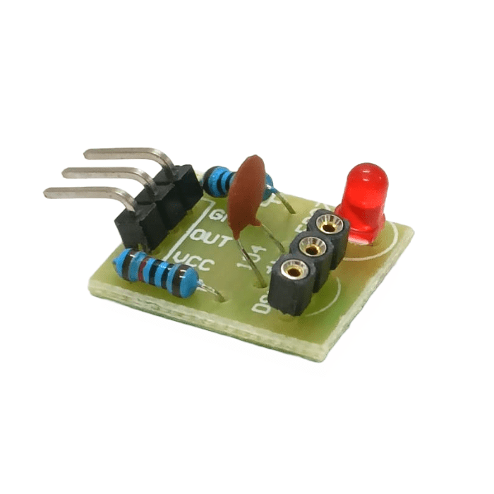
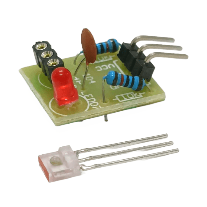
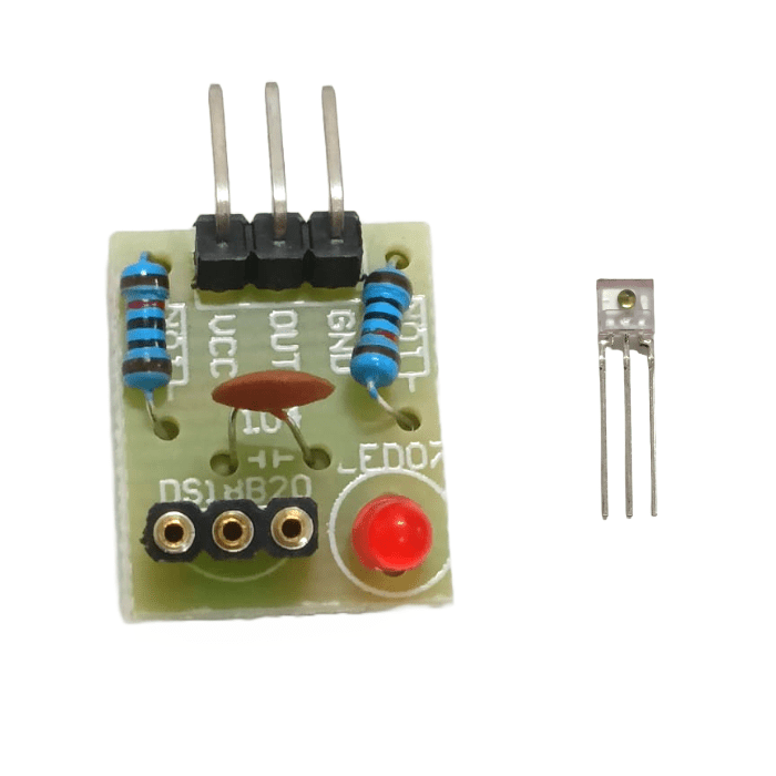
Laser Receiver Module
LASER lights have many applications like in counting, time measurement, laser guidance systems etc. It is very vital to correctly read and perform the corresponding function given in your code as any misread or malfunction in system can lead to fatal errors and losses to company. To keep this error in check this Non- Modulator Tube LASER Receiver sensor module is there to help you read the incoming laser signals accurately. It gives output of laser receiver in digital format and output pin is high when LASER is detected and low when LASER is not detected. This module works on 5V Voltage input and due to its small size you can use it in portable devices and industrial equipment.
This Laser Receiver
Sensor Module
Laser output High Level is a sensor for
Raspberry Pi
and Arduino to receive the laser output and decode it digital data. At Input, the module Receives a laser signal when output high level; Does not receive a laser signal when output low level. On detecting a laser signal, output goes at a high level (5V) until the laser signal is there.
Circuit diagram
As you can see the setup consists only one amber LED and its current limiter 10K
resistor
connected across the output of the module (OUT & VCC).
Features:
PCB Color: Green
Output high level when receiving the laser signal
Output low level when not receiving laser signal.
Application: Electronic Circuits
₹68.07
MRP. ₹110.60
Incl. GST (No Hidden Charges)
Incl. GST (No Hidden Charges)
Laser Receiver Module
Laser Receiver Module LASER lights have many applications like in counting, time measurement, laser guidance systems etc. It is very vital to correctly read and perform the corresponding function given …
As low as
₹68.07
₹68.07
MRP. ₹110.60
Incl. GST (No Hidden Charges)
LC100A 2.5inch LCD Digital Hi…
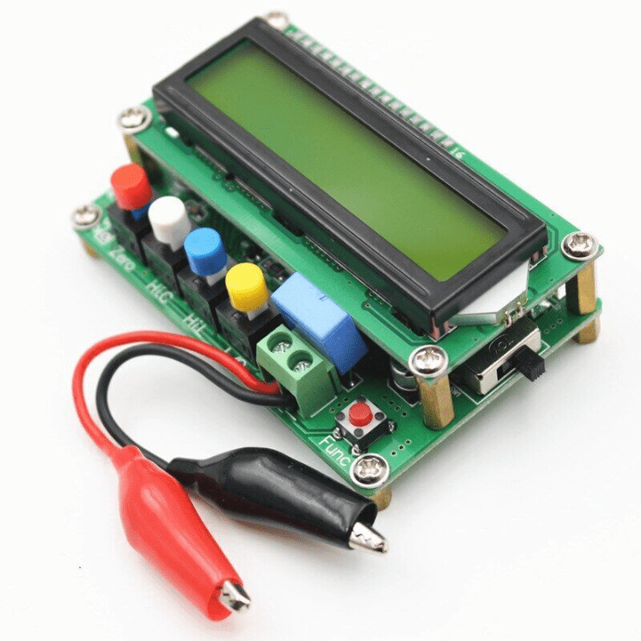
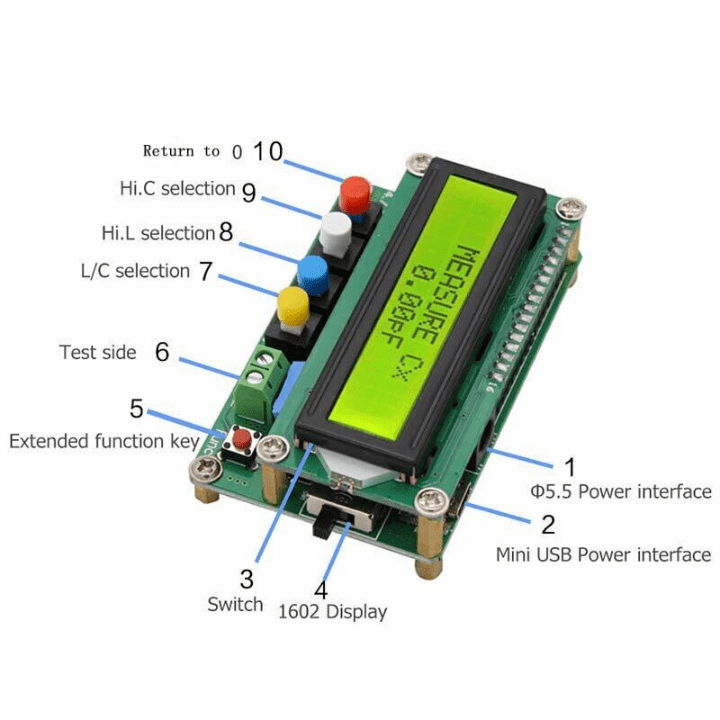
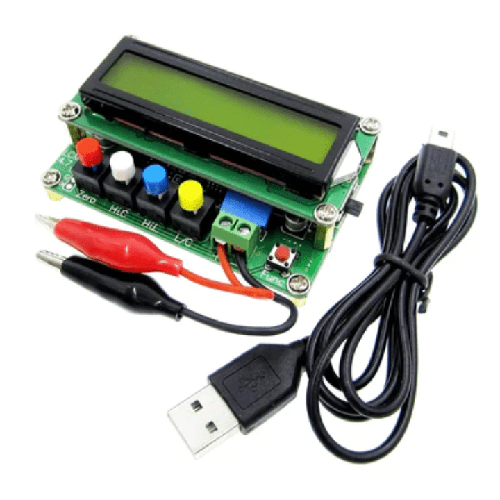
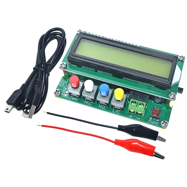
LC100A 2.5? LCD Digital High Precision Inductance Capacitance (LC) Meter
The LC100A 2.5 LCD Digital High Precision Inductance/Capacitance (L/C) Meter can measure the capacitance of 1pF-100mF and the inductance of 1uH – 100H. Based on the principle of LC resonance, this instrument incorporates the precision measurement calculation of high-speed microcontroller. It can measure the inductance below 1uH and the small capacitance less than 1pF.
Apart from measuring regular capacitor and inductor parts, an LC100-A LC meter can be the handy tool for measuring the inductance of your mini-quad motor windings, to determine if a particular motor has shorted turns or not.
The biggest feature of the LC100A 2.5 LCD Digital High Precision Inductance/Capacitance (L/C) Meter is especially suitable for microwave production and measurement of switching power supply transformers and filter inductors. This product has an absolute advantage over small-value test in comparison with the finished inductor and capacitance meter (such as 6243 series) sold on the market.
Degree and minimum resolution, and flexible online calibration can maintain measurement accuracy at any time; the instrument does not use any potentiometer adjustment. The calibration parameters are completely stored in the FLASH of the microcontroller after power loss data will not be lost. The calibration method is accurate and convenient.
To make the LC100 a bit more workbench friendly, it features a few modifications. The LC100-A expects a 5V power supply, either by the USB connector or the coaxial DC socket. With the DC input socket, there is a risk of accidentally hooking up a supply of more than 5 volts, so a 5V regulator is being fitted, so that it can be powered off anything from 7 volts to the upper limit of the regulator (usually 35 volts).
Measuring range position:
C range - Capacitance (0.01pF-10uF)
L range - Inductance (0.001uH-100mH)
HL range - Big inductance (0.001mH-100H)
HC range - Big capacitance range (1uF-100mF)
Also check the
T-66 Continuity Tester With 2 Button Cell
available on the Iotcart website. It is a multi-purpose, lightweight continuity tester designed for checking electrical wires and power between two points.
₹1455.90
MRP. ₹2728.60
Incl. GST (No Hidden Charges)
Incl. GST (No Hidden Charges)
LC100A 2.5inch LCD Digital High Precision Inductance Capacitance (LC) Meter
LC100A 2.5? LCD Digital High Precision Inductance Capacitance (LC) Meter The LC100A 2.5 LCD Digital High Precision Inductance/Capacitance (L/C) Meter can measure the capacitance of 1pF-100mF and the inductance of …
As low as
₹1455.90
₹1455.90
MRP. ₹2728.60
Incl. GST (No Hidden Charges)
LDR 5mm Metal Housing (Pack o…
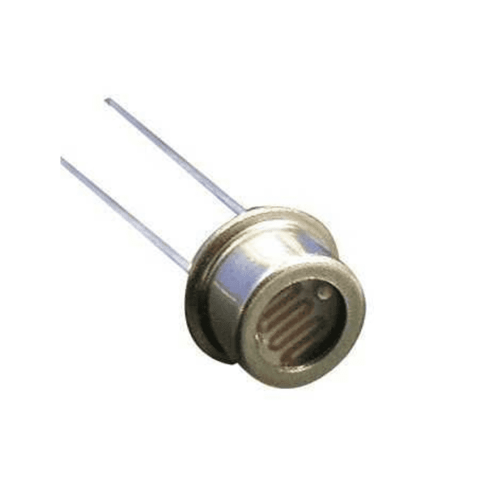
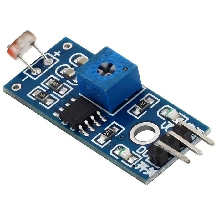
LDR 5mm Metal Housing
LDR Stands for Light Dependent Resistor and its Resistivity varies with Incident Electromagnetic Radiations so, its resistivity is a function of Incident Electromagnetic Radiations or light. Other names of LDR are photoresistor, Photoconductor, Photocell, and photo conducting cell.
LDR
sensor
5mm – Metal Housing is a
resistor
which made of semi-conductor material, and the conductance changes with luminance variation .The photoresistor can be manufactured with different figures and illuminated area based on this characteristic. Photoresistor is widely used in many industries, such as toys, lamps, camera, etc.
LDR is made of Semiconductor materials with high Resistance like Silicon or Germanium. It is a light-sensitive device, so this resistor has a different resistance value in day and night as given below:
Daylight: 5000?
Dark: 20000000?
Also, read our blog
Uses of LDR
detailing every related LDR Sensor from the definition, and working principle, to the uses of LDR sensors in a variety of projects.
Features
It requires less power to operate
Quick Response
Easy to use
Generate high current
Application
Camera Exposure Control
Auto Slide Focus
Photocopy Machines
Colorimetric Test Equipment
Densitometer
₹161.54
MRP. ₹270.20
Incl. GST (No Hidden Charges)
Incl. GST (No Hidden Charges)
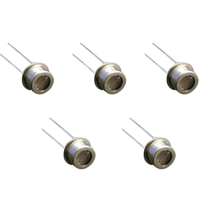
LDR 5mm Metal Housing (Pack of 5)
LDR 5mm Metal Housing LDR Stands for Light Dependent Resistor and its Resistivity varies with Incident Electromagnetic Radiations so, its resistivity is a function of Incident Electromagnetic Radiations or light. …
As low as
₹161.54
₹161.54
MRP. ₹270.20
Incl. GST (No Hidden Charges)
LDR Sensor Module
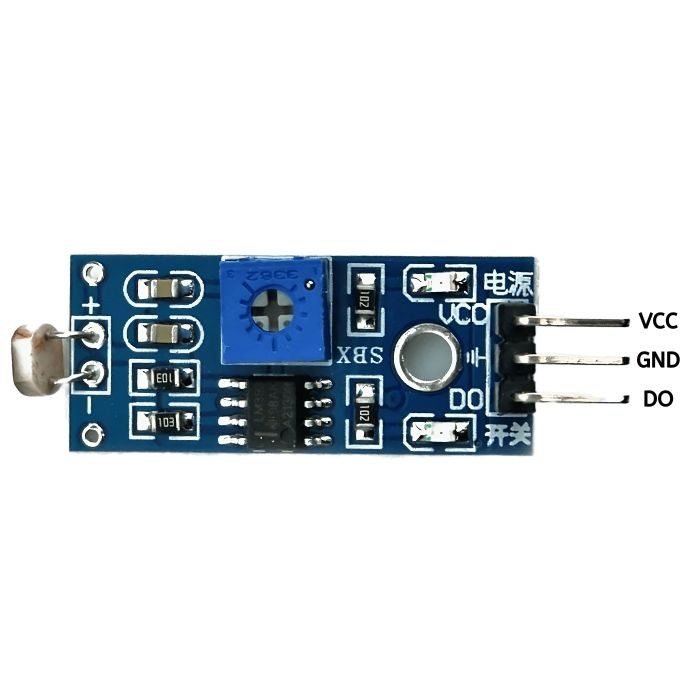
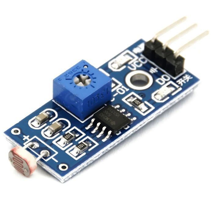
LDR Sensor Module
The LDR sensor module detects light and measures how bright it is. When there’s light, the output is high, and when there’s no light, it’s low. You can change how sensitive it is using a small dial (potentiometer).
This light detection sensor has an M3 mounting hole for easy attachment and comes with an LDR for accurate readings. The LDR module also has a power LED and a status LED to show if it’s working, making it great for checking how bright the surroundings are.
Check out our collection of
Other Sensors
!
Features:
Adjustable sensitivity via blue digital potentiometer adjustment
Digital output range: 0V to 5V
Adjustable trigger level from preset
LEDs indicating output and power (Power indicator in red and digital switch output indicator in green)
Uses LM393 comparator chip for stability
Easy to install with an M3 mounting hole for attachment
Suitable for detecting ambient brightness and light intensity
Digital output for easy integration with microcontrollers
Comes with a power LED and status LED as indicators
Applications:
Control lights with LDR sensors.
Adjust streetlights for energy savings.
Trigger alarms in security.
Monitor sunlight for plants.
Optimize camera settings.
Pinout:
Pin No
Pin Name
Description
1
VCC
3.3V to 5V DC power supply
2
GND
Ground
3
DO
Digital output
How to Use:
A photosensitive resistor module most sensitive to environmental light intensity is generally used to detect the ambient brightness and light intensity.
Module light conditions or light intensity reach the set threshold, DO port output is high when the external ambient light intensity exceeds a set threshold, the module D0 output is low;
Digital output D0 is directly connected to the MCU, and detects high or low TTL, thereby detecting ambient light intensity changes;
Digital output module DO can directly drive the relay module, which can be composed of a photoelectric switch;
Read our blog explaining
how LDR works.
₹30.48
MRP. ₹61.60
Incl. GST (No Hidden Charges)
Incl. GST (No Hidden Charges)

LDR Sensor Module
LDR Sensor Module The LDR sensor module detects light and measures how bright it is. When there’s light, the output is high, and when there’s no light, it’s low. You …
As low as
₹30.48
₹30.48
MRP. ₹61.60
Incl. GST (No Hidden Charges)
LDR Sensor Module (Pack of 25)
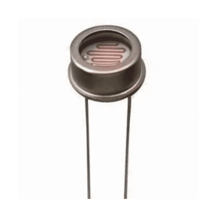
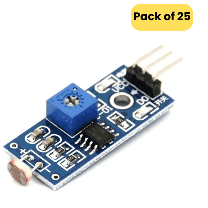
LDR Sensor Module
The LDR sensor Module is used to detect the presence of light and measure the intensity of light. The output of the module goes high in the presence of light and it becomes low in the absence of light. The sensitivity of signal detection can be adjusted using the potentiometer. You can adjust the threshold (sensitivity) of the digital output by tuning the onboard variable resistor (potentiometer). Simple usage as it is the digital output, so you will know the light present and decide what to do with it.
LDR sensor Module comes with an M3 mounting hole for ease of attaching it to an object. Onboard, it provides an LDR, high sensitivity and commonly being used for light detection. The module comes with a power LED and a status LED as an indicator. LDR Module Photosensitive resistor module most sensitive to environmental light intensity is generally used to detect the ambient brightness and light intensity.
If you want to use the LDR module in your projects, then you will need a few essential components like an
Arduino
,
relays
,
breadboard
and
jumper wires
.
LDR Sensor Module pin diagram
Pin No
Pin Name
Description
1
VCC
3.3V to 5V DC power supply
2
GND
Ground
3
DO
Digital output
How to Use:
A photosensitive resistor module most sensitive to environmental light intensity is generally used to detect the ambient brightness and light intensity.
Module light conditions or light intensity reach the set threshold, DO port output high when the external ambient light intensity exceeds a set threshold, the module D0 output low;
Digital output D0 is directly connected to the MCU, and detects high or low TTL, thereby detecting ambient light intensity changes;
Digital output module DO can directly drive the relay module, which can be composed of a photoelectric switch;
₹659.37
MRP. ₹1398.60
Incl. GST (No Hidden Charges)
Incl. GST (No Hidden Charges)

LDR Sensor Module (Pack of 25)
LDR Sensor Module The LDR sensor Module is used to detect the presence of light and measure the intensity of light. The output of the module goes high in the …
As low as
₹659.37
₹659.37
MRP. ₹1398.60
Incl. GST (No Hidden Charges)
Led Combo (R-G-Y-B-W) 5mm 10p…
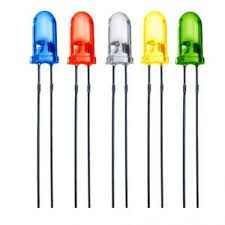
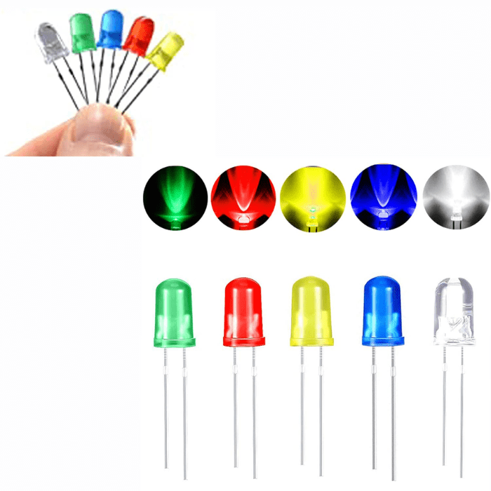
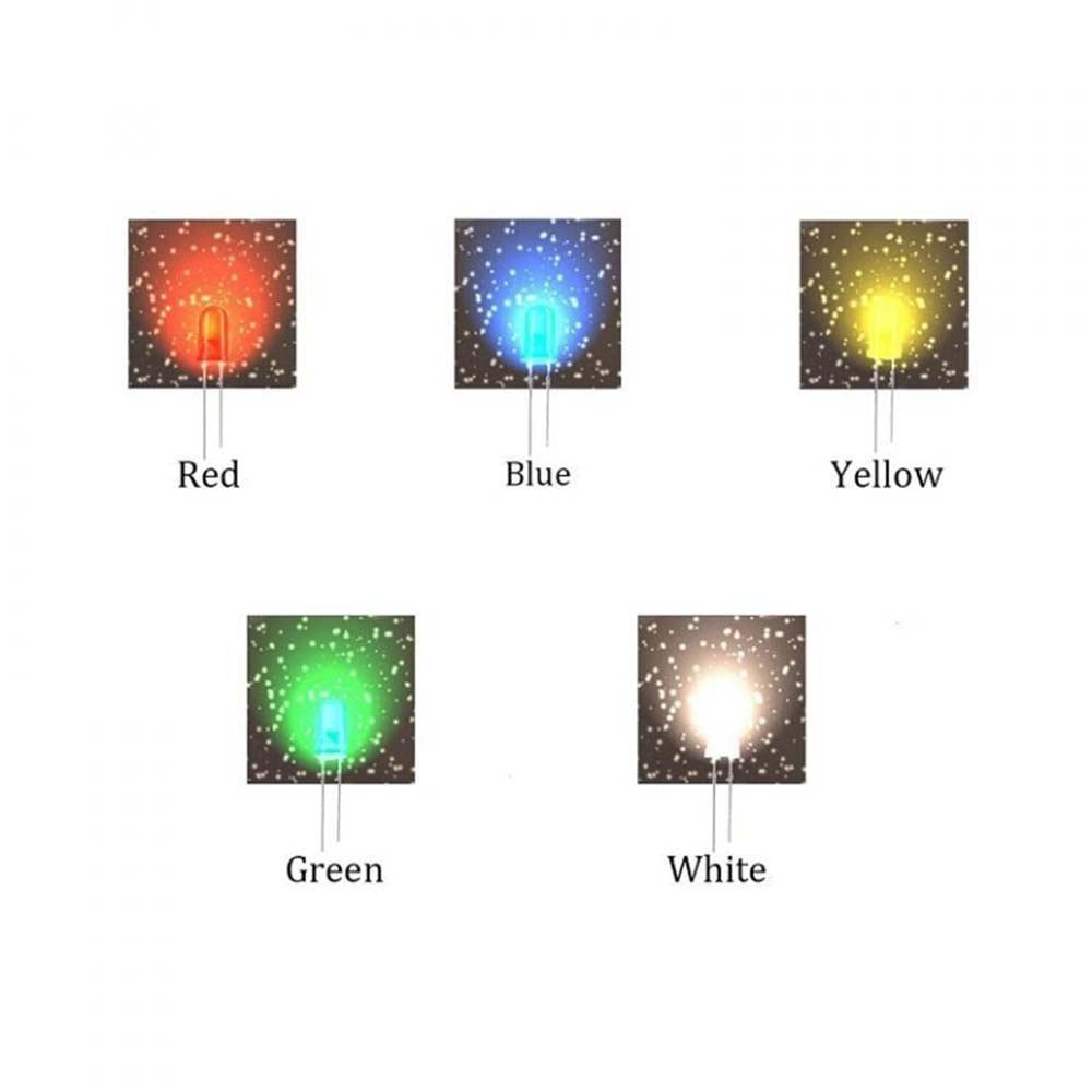
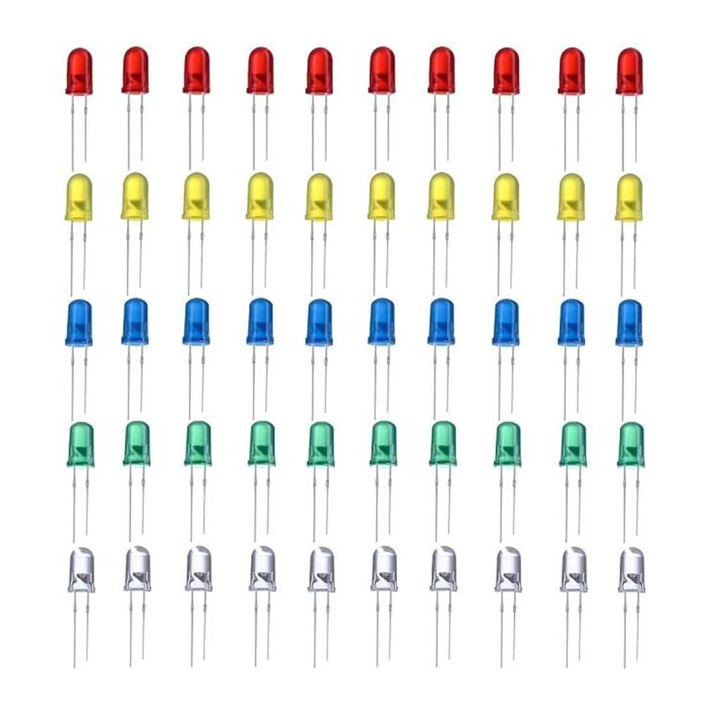
Led Combo (R-G-Y-B-W) 5mm
LEDs are used as indicator lamps in many devices and are increasingly used for other lighting. It looks like a white LED and illuminates blue light. When a light-emitting diode is switched on, electrons are able to recombine with holes within the device, releasing energy in the form of photons. This effect is called electroluminescence and the colour of the light (corresponding to the energy of the photon) is determined by the energy bandgap of the semiconductor.
It is good quality and durable & small size and super bright LEDs with Low heat dissipation, energy-saving, and a long lifespan. These LEDs are always in demand in the DIY community as well as in industrial applications.
Applications:
DIY LED projects
School science experiments
Automobile decorations
Electronic and electrical experiments
₹98.55
MRP. ₹208.60
Incl. GST (No Hidden Charges)
Incl. GST (No Hidden Charges)

Led Combo (R-G-Y-B-W) 5mm 10pcs each
Led Combo (R-G-Y-B-W) 5mm LEDs are used as indicator lamps in many devices and are increasingly used for other lighting. It looks like a white LED and illuminates blue light. …
As low as
₹98.55
₹98.55
MRP. ₹208.60
Incl. GST (No Hidden Charges)
