

Sort by
NRF24L01 Adapter Board
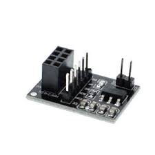
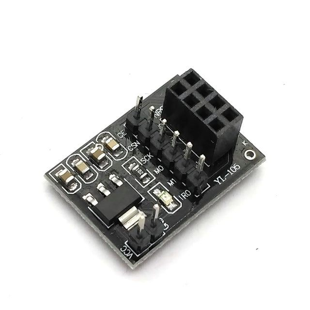
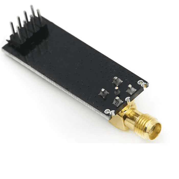
NRF24L01 Adapter Board
With the 3.3V VCC Adapter Board, you can utilize NRF24l01 type transceivers on 5V systems, such as Arduino. It functions by regulating the 3.3V input to 1.9~3.6V DC and includes bypass capacitors for dependable operation.
This adapter board is particularly designed to work with the NRF24L01
transceiver
module and features the Enhanced ShockBurst (ESB) protocol. It supports two-way data packet communication with packet buffering, packet acknowledgement, and automatic re-transmission of lost packets.
Features
It can be used with NRF24L01 wireless module
Add core nRF24L01+ Breakout Adapter with onboard 3.3V Regulator
Onboard 3.3V voltage regulator accepts your Arduino +5V supply and provides 3.3V for the attached nRF24L01+ module
Allows for easy connection to nRF24L01+ modules
Small power on SMD LED indicator
On-Board Voltage Regulator:
Voltage Regulator Input Voltage (connected to VCC): 4.8V to 12V
Voltage Regulator Input Voltage Max: 15V (we recommend staying below 12V)
₹38,94
MRP. ₹68,60
Incl. GST (No Hidden Charges)
Incl. GST (No Hidden Charges)
NRF24L01 Adapter Board
NRF24L01 Adapter Board With the 3.3V VCC Adapter Board, you can utilize NRF24l01 type transceivers on 5V systems, such as Arduino. It functions by regulating the 3.3V input to 1.9~3.6V …
As low as
₹38,94
₹38,94
MRP. ₹68,60
Incl. GST (No Hidden Charges)
NRF24L01 Ultra Low Power 2.4G…
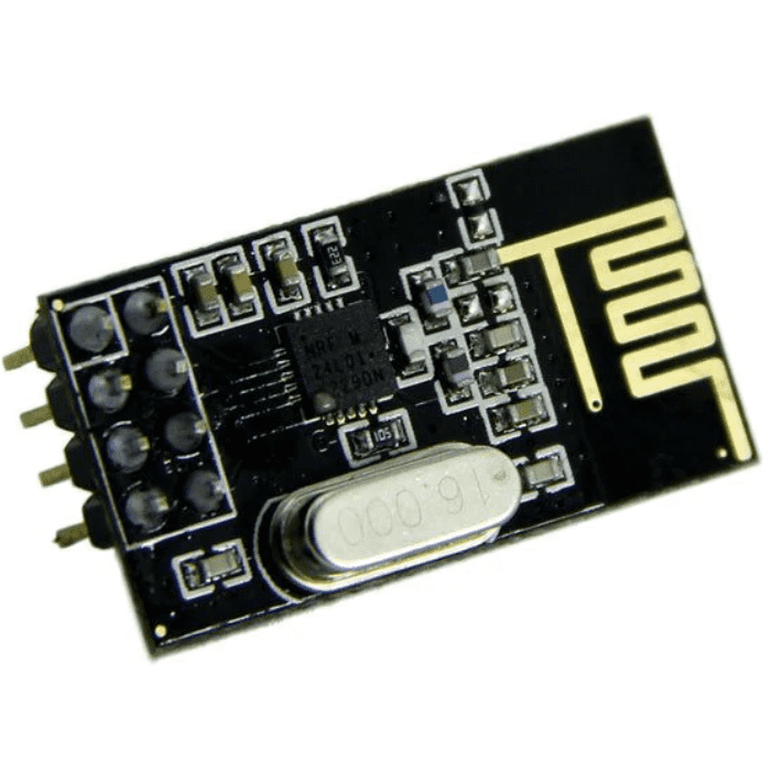
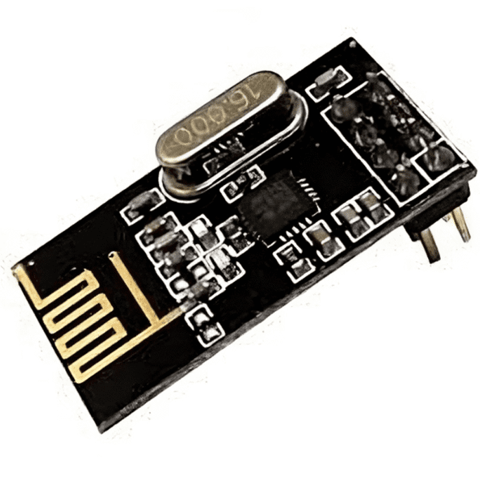
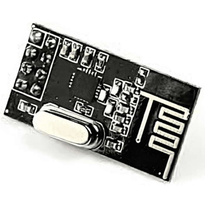
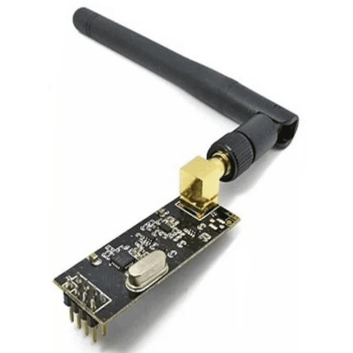
NRF24L01 Ultra-Low Power 2.4GHz RF Wireless Transceiver
The NRF24L01 2.4GHz Antenna Wireless Transceiver Module is a compact and integrated IC designed for ultra-low power (ULP) RF transmission and reception in the 2.4GHz ISM band. It boasts a peak current of less than 14mA for both receiving and transmitting, a sub ?A power down mode, advanced power management, and a wide supply voltage range of 1.9 to 3.6V, which makes it a true ULP solution for achieving extended battery life, especially when running on coin cells or AA/AAA batteries.
These
RF modules
are widely used by Arduino enthusiasts and are suitable for various wireless control applications, given their transceiver nature, allowing for data transmission and reception. The NRF24L01+ 2.4GHz Antenna Wireless Transceiver Module is compatible with different MCUs, including Arduino, Mbed, and ARM. It can be easily powered by mounting it over a 3.3V Adapter Board designed for the 24L01 Wireless Module.
Features :
Maximum operating speeds up to 2Mbps, GFSK modulation efficiency, Anti-interference ability,
Particularly suitable for industrial control applications.
125 Channels, Multi-point communication, and frequency hopping to meet the communication needs
Built-in hardware CRC error detection, Multipoint communication address control.
Low-power 1.9 ~ 3.6V, only 1uA on Power down mode
Built-in 2.4Ghz antenna
Available software to set the address only received local Address when output data(Provide interrupt instruction), can be directly connected to a variety of microcontrollers, Software programming is very convenient.
Built-in voltage regulator
Standard DIP Pitch Interface for embedded applications.
read our blog explaining the
nrf24l01 pinout
, which provides detailed information about the NRF24L01 wireless communication module, including its operations, features, applications, and versions.
Note:
VCC is a range of 1.9V~3.6V, do not exceed this range, otherwise, it will destroy the module.
Communication pins other than Vcc and GND are 5v tolerant
Applications:
Wireless PC Peripherals
Mouse, keyboards, and remotes
3-in-1 desktop bundles
Advanced Media center remote controls
VoIP headsets
Game controllers
Sports watches and sensors
RF remote controls for consumer electronics
Home and commercial automation
Ultra low power sensor networks
Active RFID
Alarm and security systems
Asset tracking systems
Toys
₹73,44
MRP. ₹166,60
Incl. GST (No Hidden Charges)
Incl. GST (No Hidden Charges)

NRF24L01 Ultra Low Power 2.4GHz RF Wireless Transceiver
NRF24L01 Ultra-Low Power 2.4GHz RF Wireless Transceiver The NRF24L01 2.4GHz Antenna Wireless Transceiver Module is a compact and integrated IC designed for ultra-low power (ULP) RF transmission and reception in …
As low as
₹73,44
₹73,44
MRP. ₹166,60
Incl. GST (No Hidden Charges)
NRF24L01 Ultra Low Power 2.4G…
NRF24L01 Ultra-Low Power 2.4GHz RF Wireless Transceiver
The NRF24L01 2.4GHz Antenna Wireless Transceiver Module is a compact and integrated IC designed for ultra-low power (ULP) RF transmission and reception in the 2.4GHz ISM band. It boasts a peak current of less than 14mA for both receiving and transmitting, a sub ?A power down mode, advanced power management, and a wide supply voltage range of 1.9 to 3.6V, which makes it a true ULP solution for achieving extended battery life, especially when running on coin cells or AA/AAA batteries.
These
RF modules
are widely used by Arduino enthusiasts and are suitable for various wireless control applications, given their transceiver nature, allowing for data transmission and reception. The NRF24L01+ 2.4GHz Antenna Wireless Transceiver Module is compatible with different MCUs, including Arduino, Mbed, and ARM. It can be easily powered by mounting it over a 3.3V Adapter Board designed for the 24L01 Wireless Module.
Features :
Maximum operating speeds up to 2Mbps, GFSK modulation efficiency, Anti-interference ability,
Particularly suitable for industrial control applications.
125 Channels, Multi-point communication, and frequency hopping to meet the communication needs
Built-in hardware CRC error detection, Multipoint communication address control.
Low-power 1.9 ~ 3.6V, only 1uA on Power down mode
Built-in 2.4Ghz antenna
Available software to set the address only received local Address when output data(Provide interrupt instruction), can be directly connected to a variety of microcontrollers, Software programming is very convenient.
Built-in voltage regulator
Standard DIP Pitch Interface for embedded applications.
Note:
VCC is a range of 1.9V~3.6V, do not exceed this range, otherwise, it will destroy the module.
Communication pins other than Vcc and GND are 5v tolerant
Applications:
Wireless PC Peripherals
Mouse, keyboards, and remotes
3-in-1 desktop bundles
Advanced Media center remote controls
VoIP headsets
Game controllers
Sports watches and sensors
RF remote controls for consumer electronics
Home and commercial automation
Ultra low power sensor networks
Active RFID
Alarm and security systems
Asset tracking systems
Toys
₹2001,82
Incl. GST (No Hidden Charges)
Out of Stock
MRP. ₹3430,00
Incl. GST (No Hidden Charges)

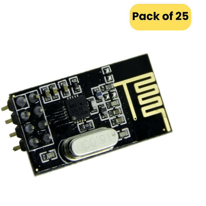
NRF24L01 Ultra Low Power 2.4GHz RF Wireless Transceiver ( Pack of 25)
NRF24L01 Ultra-Low Power 2.4GHz RF Wireless Transceiver The NRF24L01 2.4GHz Antenna Wireless Transceiver Module is a compact and integrated IC designed for ultra-low power (ULP) RF transmission and reception in …
As low as
₹2001,82
₹2001,82
MRP. ₹3430,00
Incl. GST (No Hidden Charges)
Out of Stock
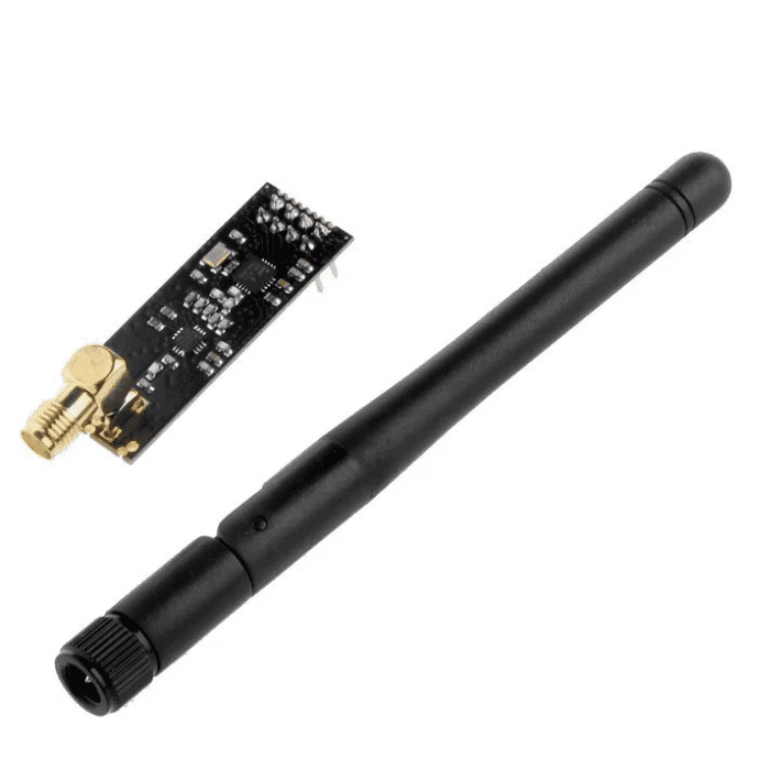
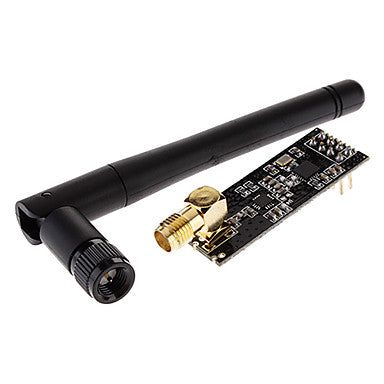
NRF24L01+PA+LNA
NRF24L01+PA+LNA SMA Wireless Transceiver Antenna
The NRF24L01 module is a state-of-the-art RF module that uses Nordic Semiconductor's 2.4GHz
transceiver
, the NRF24L01+. This IC operates in the 2.4GHz band and comes with many new features, such as additional pipelines, buffers, and an auto-retransmit function. The board has a reverse-polarized SMA connector that maximizes the RF range, as well as a PA and LNA circuit, which enables long-distance communication when combined with an external antenna.
The module comes with a 2DB 2.4G antenna and can achieve a communication distance of 800-1K meters with a transmission rate of 250Kbps on open-air. It is an affordable and user-friendly option for setting up a wireless communication system, striking a good balance between cost and wireless transition performance.
The nRF24L01+ module is compatible with various systems, including MCU/ARM/PIC/AVR/STM32, and its power amplifier and SMA antenna design allow for wireless communication up to 1000 meters without barriers.
Features :
It uses 2.4GHz global open ISM band, with license-free.
Transmit power is greater than +20 dBm.
Support six-channel data reception.
2Mbit/s speed makes high-quality VoIP possible
Multi-frequency points: 125 frequency points meet the needs of multi-point communications and frequency hopping.
Low cost: integrated with high-speed signal processing parts associated with RF protocol, such as: automatically re-send lost packets and generate acknowledge signal;
SPI interface facilitates the communication with MCU I/O port.
Facilitate the development for customers, without development RF part.
Software programming is fully compatible with NRF24L01 modules.
₹155,78
Incl. GST (No Hidden Charges)
Out of Stock
MRP. ₹278,60
Incl. GST (No Hidden Charges)
NRF24L01+PA+LNA
NRF24L01+PA+LNA SMA Wireless Transceiver Antenna The NRF24L01 module is a state-of-the-art RF module that uses Nordic Semiconductor's 2.4GHz transceiver , the NRF24L01+. This IC operates in the 2.4GHz band and …
As low as
₹155,78
₹155,78
MRP. ₹278,60
Incl. GST (No Hidden Charges)
Out of Stock
Original Mastech MS830L Digit…
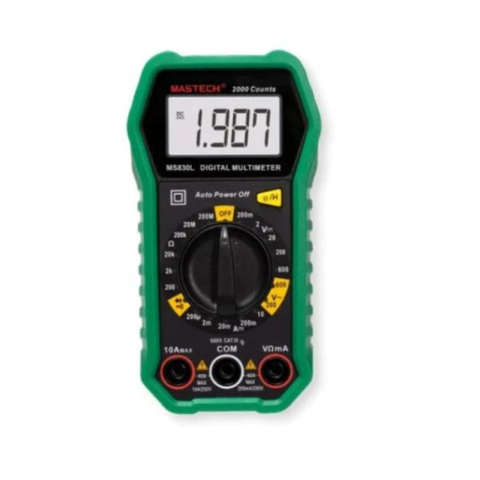
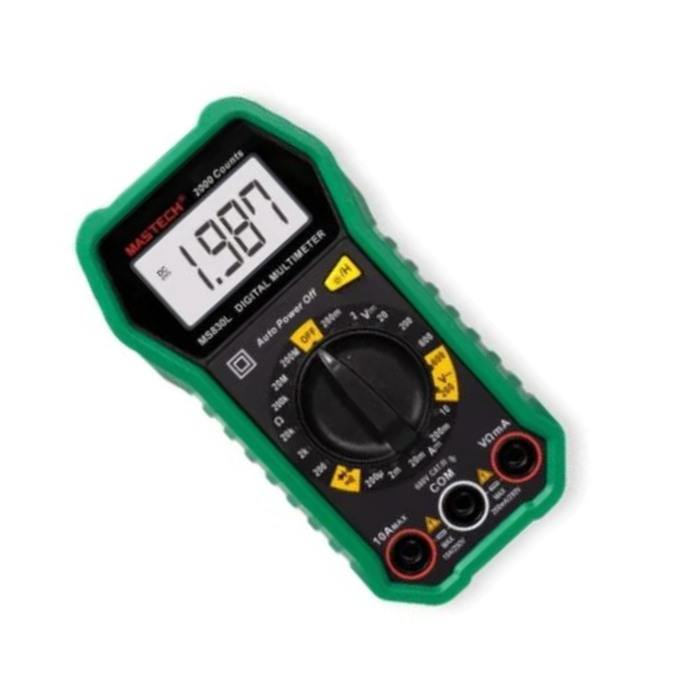
Original Mastech MS830L Digital Pocket Multimeter with Probes
It is a handheld Digital Mastech Multimeter for measuring DC and AC Voltage, DC Current, Resistance, Diode, and Transistor with battery operation. The Mastech MS830L Digital Multimeter has a Blue Backlight LCD with 1999 counts and 2-3/sec updates Measuring method. It features a dual-slope integration A/D Converter.
Safety Measures for MS830L:
Failing these Precautions May Lead to Instrument Damage
Always make sure the Test Probes are fitted in the correct sockets (Especially while measuring AC Voltage )
Please choose the correct measuring option before you connect the probe. (As a thumb rule always choose the greater value and decrease if required)
While measuring current, make sure to put the Red Probe in the “10A” socket and the measuring connection should be in “Series”
While measuring all other parameters other than Current (Ampere), the measuring connection should be in “Parallel”
If by mistake a wrong connection or option is selected and the measurement is initiated, the instrument will Blink / Beep. Remove the connections immediately to restrict the damage to a minimum
The instrument can only be used in conjunction with the probe for compliance with safety standards. If the probe needs replacing due to damage, the replacement must be of the same type or the same electrical specifications
Do not exceed the input limits specified for each range
When the instrument is measuring, do not touch the input terminal, not in use
When a measurement range is uncertain, turn the function/range switch to the maximum range position
Features:
Measurement Capabilities: Measures DC and AC voltage, DC current, resistance, diode, and transistor.
Display: Blue backlight LCD display with 1999 counts, updating 2-3 times per second.
Power Source: Operates on a 9V battery (NEDA 1604 or 6F22 type).
Data Hold Function: Allows you to freeze the displayed reading for easy recording.
Continuity Buzzer: Audible alert for continuity testing.
Low Battery Indicator: Displays a warning when the battery is low.
Compact Size: Pocket-sized design for portability and convenience.
Applications:
Electrical Troubleshooting
DIY Electronics Projects
Automotive Testing
Home Appliance Repair
Educational Purposes
Field Service
Measurement:
DC Voltage up to 600V (In 5 Ranges)
AC Voltage up to 600V (In 2 Ranges)
DC Current up to 10A (In 5 Ranges)
Resistance up to 2 M.OHMS (In 5 Ranges)
₹820,09
MRP. ₹1398,60
Incl. GST (No Hidden Charges)
Incl. GST (No Hidden Charges)
Original Mastech MS830L Digital Pocket Multimeter with Probes
Original Mastech MS830L Digital Pocket Multimeter with Probes It is a handheld Digital Mastech Multimeter for measuring DC and AC Voltage, DC Current, Resistance, Diode, and Transistor with battery operation. …
As low as
₹820,09
₹820,09
MRP. ₹1398,60
Incl. GST (No Hidden Charges)
OV7670 VGA Camera Module
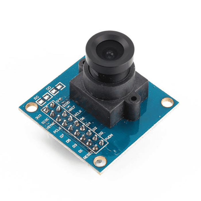
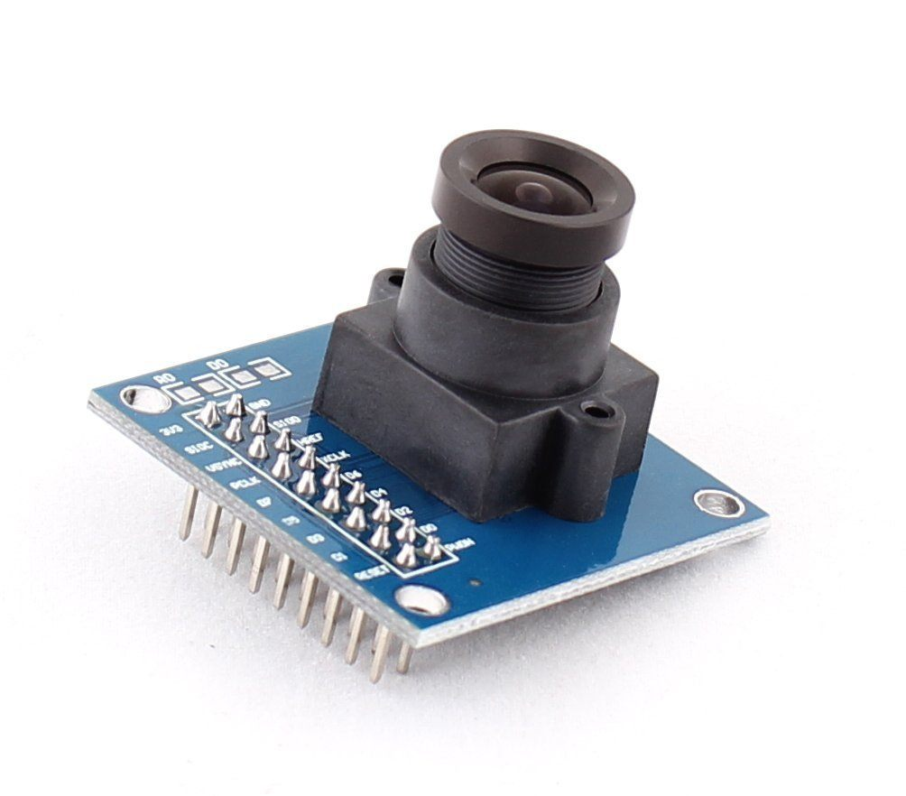
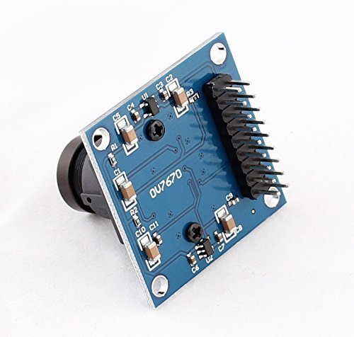
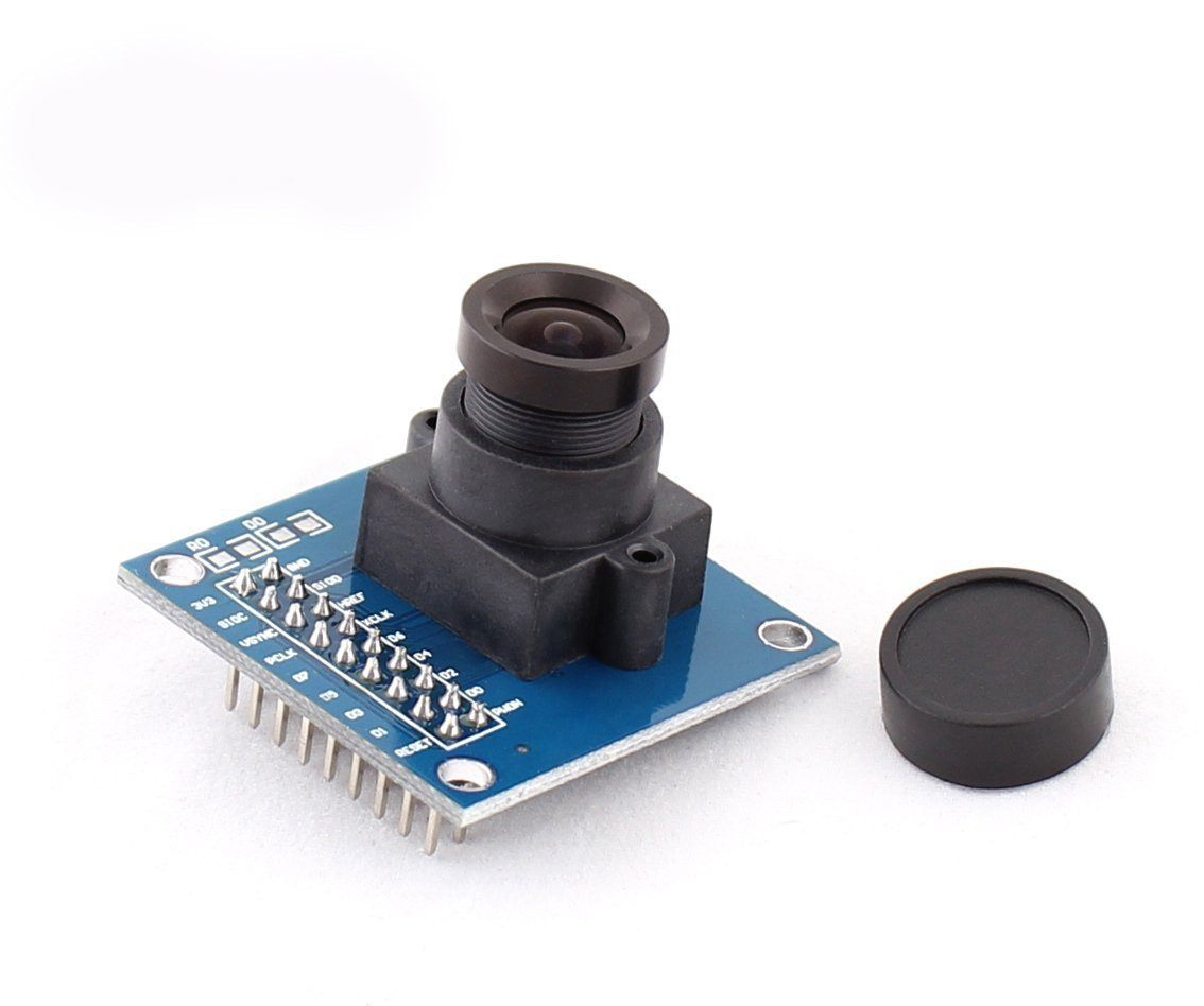
OV7670 VGA Camera Module
OV7670 VGA Camera Module is a low-cost image sensor, DSP that can operate at a maximum of 30 fps and 640 x 480 (“VGA”) resolutions, equivalent to 0.3 Megapixels.
The captured image can be pre-processed by the DSP before sending it out. This pre-processing can be configured via the Serial Camera Control Bus (SCCB). OmniVision OV7670 CMOS VGA (640×480) CAMERA-CHIP Sensor with OmniPixel technology 3.3V DC Input Voltage. working Temp. 0-50 Degree Celsius All Glass Lenses, Lens(including seat) is Magnesium Alloy material.
The focal length of the lens is 3.6 mm 650 nm Bands Black FR-4 PCB, Quality Heavy Gold Plate, effectively prevent the PCB from light leak issues and prevents shadow in images 2×10 0.1? output connector for convenient insertion into Prototype Board, Bread Board, MCU Onboard Connectors This Camera module is very powerful and easy-to-interface with 8/16/32 bit Micro-controller. OV7670 640X480 VGA CMOS CAMERA IMAGE
SENSOR MODULE
will provide vision to your small embedded systems and will be useful for plenty of applications in Robotics.
Image Processing, Simple Machine Vision, Object Detection, Color detection, etc. 2×10 0.1? Output Connector will be easy to plug into any prototype board or breadboard which will make your project/product implementation fast. Technical parameters: High sensitivity for low-light operation Low operating voltage for embedded portable apps Lens shading correction Flicker (50/60 Hz) auto-detection Saturation level auto adjust (UV adjust) Edge enhancement level auto-adjust.
Get the
ESP32-CAM WiFi Module
for less today!
Connection Diagram:
Applications
Cellular phone
Facial Recognition
Document scanning
Surveillance systems
Obstacle avoidance
₹140,21
MRP. ₹278,60
Incl. GST (No Hidden Charges)
Incl. GST (No Hidden Charges)
OV7670 VGA Camera Module
OV7670 VGA Camera Module OV7670 VGA Camera Module is a low-cost image sensor, DSP that can operate at a maximum of 30 fps and 640 x 480 (“VGA”) resolutions, equivalent …
As low as
₹140,21
₹140,21
MRP. ₹278,60
Incl. GST (No Hidden Charges)
Owon HDS242 40 MHz Handheld D…
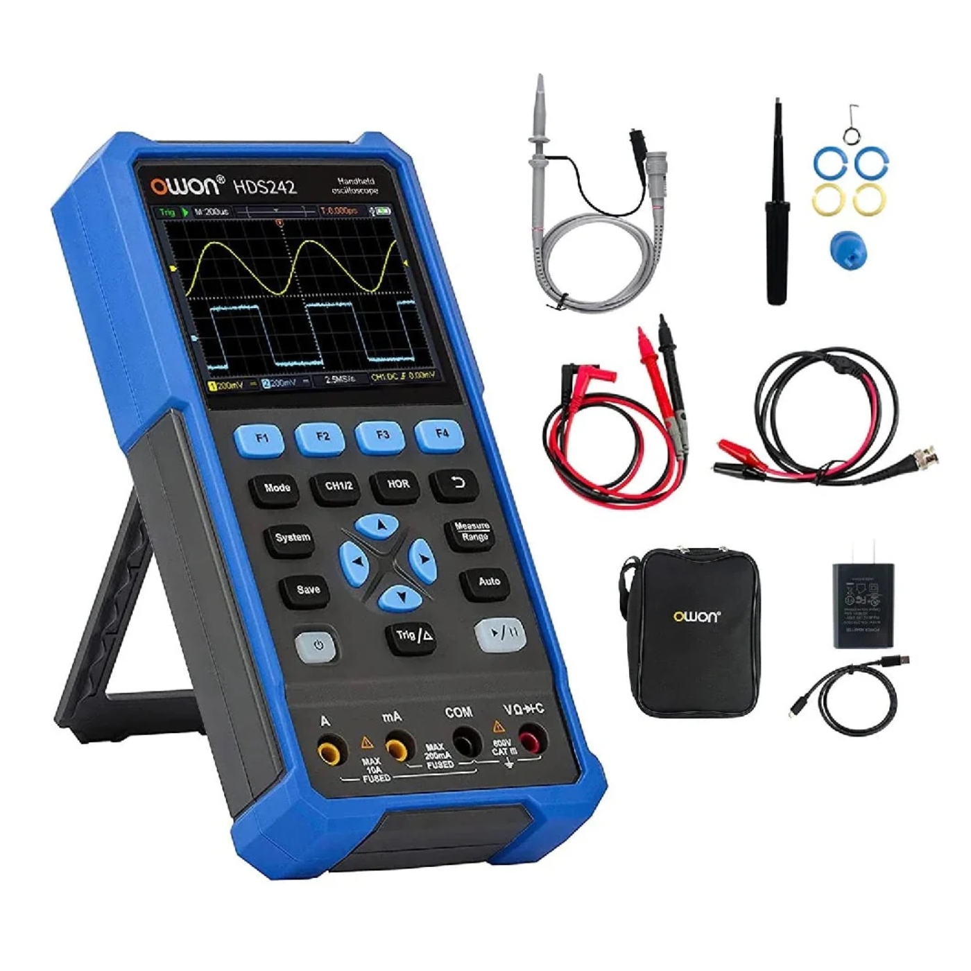
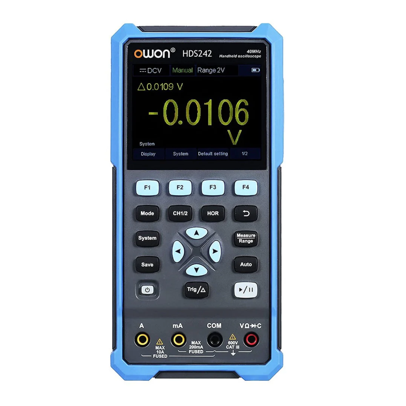
Owon HDS242 40 MHz Handheld Digital Multimeter
The HDS242 is a portable dual-channel oscilloscope that can also be used as a multimeter and a function generator. The meter sports a 3.5" high-contrast colour display suitable for outdoor use and it runs on a pair of 18650 batteries, good for up to 6 hours of continuous use. You can hook up the meter to a PC host with USB-C to use it with Owon's desktop software, control it via SCPI or to use it with a power bank.
Besides being an oscilloscope, it independently acts as a fully featured 20,000 count True-RMS multimeter. It has the capability to measure voltage, current, resistance, capacitance, continuity and diodes. The readings will be displayed comfortably large on the display.
check out :
Owon HDS272S 70 MHz Handheld Digital Multimeter
Features
40 MHz dual-channel bandwidth with up to 250 MS/s sample rate for detailed waveform capture.
Combines oscilloscope and true-RMS multimeter functions with USB-C detachable power and PC interface.
3.5″ high-contrast color LCD display designed for outdoor use; powered by 18650 lithium batteries for approximately 6 hours of operation.
Memory depth of 8 kpts (single channel) / 4 kpts (dual channel); waveform refresh rate up to 10,000 wfm/s.
Multi-mode trigger (Edge Auto/Normal/Single) and full multimeter readings including DC/AC voltage, current, resistance, continuity, and diode test.
USB-C interface with SCPI support for secondary development, PC connectivity, and firmware upgrades
Application
Field service & troubleshooting:
Ideal for on-site electronics repair, signal tracing, and maintenance work.
Education & training:
Perfect for labs and students learning signal analysis, circuit testing, and debugging.
Embedded system development:
Great for monitoring microcontroller outputs, sensor signals, and communication lines.
Industrial applications:
Suitable for factory diagnostics, control board testing, and automation system checks.
Hobby electronics & DIY:
Excellent tool for makers working with Arduino, Raspberry Pi, or robotics projects.
₹13351,77
MRP. ₹23028,60
Incl. GST (No Hidden Charges)
Incl. GST (No Hidden Charges)
Owon HDS242 40 MHz Handheld Digital Multimeter
Owon HDS242 40 MHz Handheld Digital Multimeter The HDS242 is a portable dual-channel oscilloscope that can also be used as a multimeter and a function generator. The meter sports a …
As low as
₹13351,77
₹13351,77
MRP. ₹23028,60
Incl. GST (No Hidden Charges)
Owon HDS272S 70 MHz Handheld …
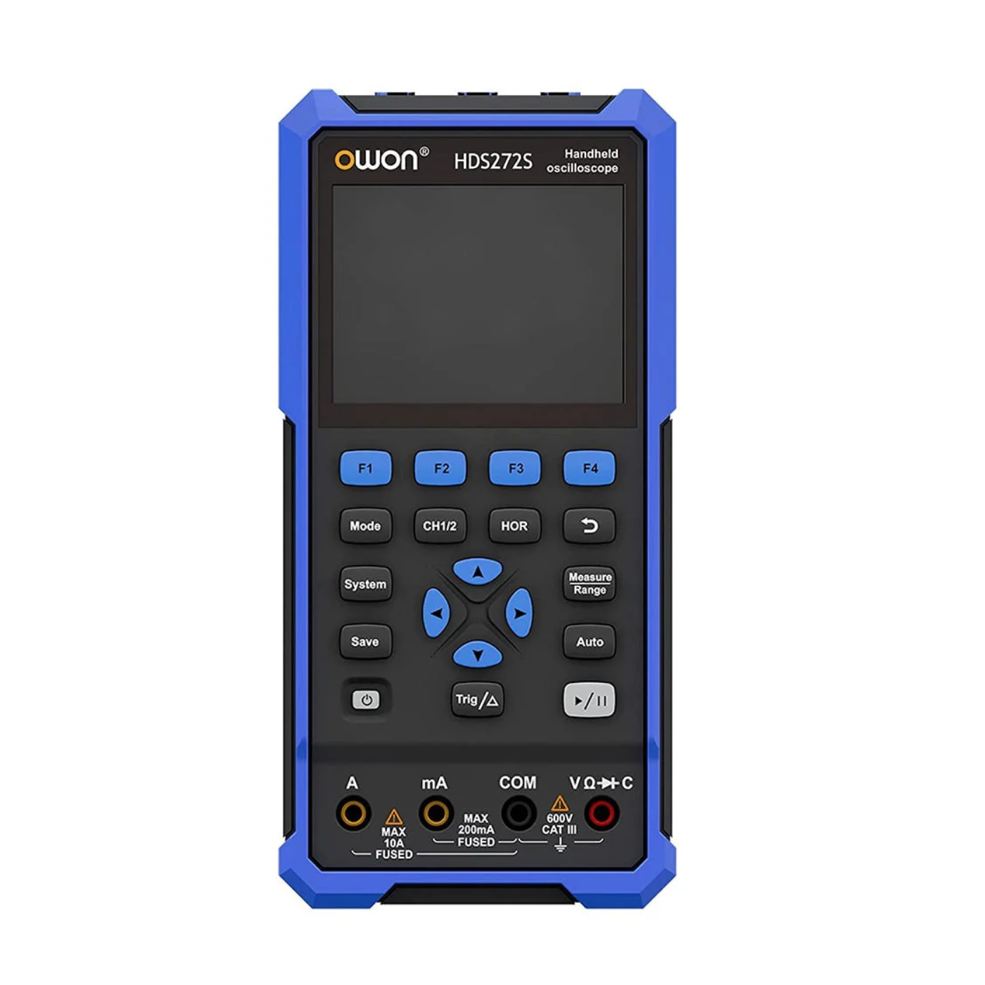
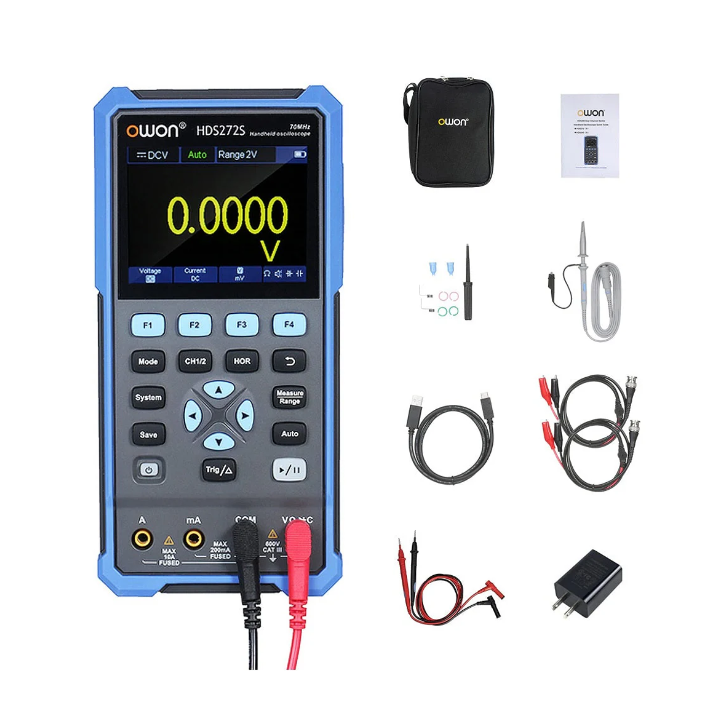
Owon HDS272S 70 MHz Handheld Digital Multimeter
The HDS272S is a portable dual-channel oscilloscope that can also be used as a multimeter and a function generator. The meter sports a 3.5" high-contrast colour display suitable for outdoor use and it runs on a pair of 18650 batteries, good for up to 6 hours of continuous use. You can hook up the meter to a PC host with USB-C to use it with Owon's desktop software, control it via SCPI or to use it with a power bank.
Features
70 MHz Dual-Channel Bandwidth :
Captures wide frequency signals with up to 250 MS/s sample rate per channel for precise waveform analysis.
3-in-1 Functionality :
Combines oscilloscope, true-RMS multimeter, and waveform generator for versatile testing in one compact device.
High-Contrast 3.5-inch Color LCD :
Easy to read in various lighting conditions; supports outdoor work and USB-C power support for portability.
Long Battery Life & USB-C Charging :
Equipped with 18650 lithium batteries, providing up to ~6 hours of continuous use, with USB-C input for power banks.
Advanced Measurement Features :
Includes 8k record length, up to 10,000 waveform refreshes per second, cursor and auto-measurements (frequency, period, amplitude).
Modern Connectivity & Expansion :
USB-C interface for PC connectivity, SCPI command support for automation, and built-in function generator for signal output.
Applications
Field Testing & Maintenance :
Ideal for on-site electronic diagnostics and system troubleshooting.
Education & Training :
Great for engineering students and labs learning circuit analysis and signal behavior.
Embedded System Debugging :
Helps in analyzing sensor outputs, serial communication signals, and digital circuits.
Industrial Equipment Testing :
Suitable for monitoring and maintaining industrial automation and control systems.
DIY & Hobby Projects :
Perfect for electronics enthusiasts working on Arduino, Raspberry Pi, or IoT projects.
₹25229,16
MRP. ₹41998,60
Incl. GST (No Hidden Charges)
Incl. GST (No Hidden Charges)
Owon HDS272S 70 MHz Handheld Digital Multimeter
Owon HDS272S 70 MHz Handheld Digital Multimeter The HDS272S is a portable dual-channel oscilloscope that can also be used as a multimeter and a function generator. The meter sports a …
As low as
₹25229,16
₹25229,16
MRP. ₹41998,60
Incl. GST (No Hidden Charges)
PCA9685 16 Channel 12 Bit Ser…
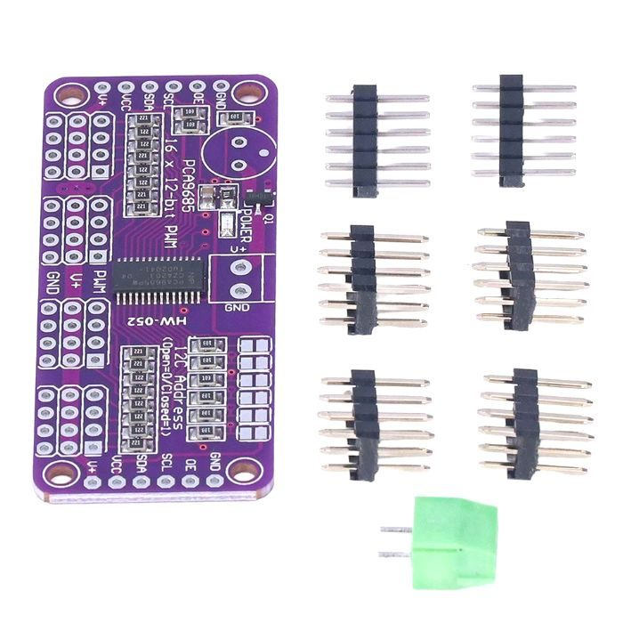
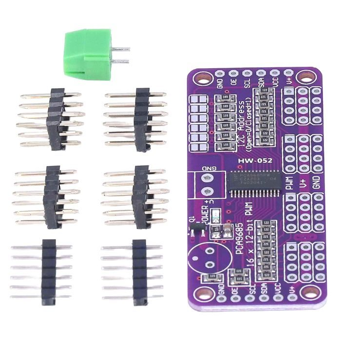
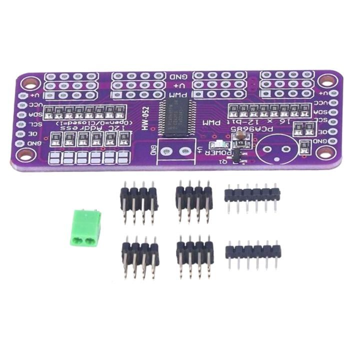
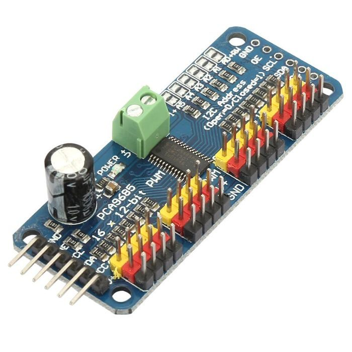
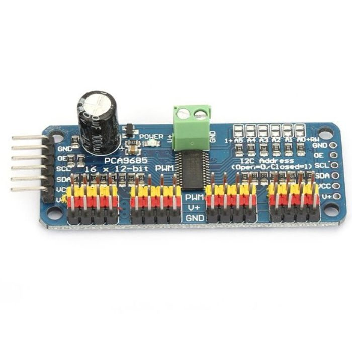
PCA9685 16 Channel 12 Bit Servo Motor Driver
This is the PCA9685 16 Channel 12 Bit Servo Motor Driver, With just two pins, you can control 16 free-running PWM outputs. Do you want to build a robot or a hexapod walker? Perhaps you're creating a work of art with many moving parts, or you need to drive a large number of LEDs with precise PWM output. Your microcontroller has a limited number of PWM outputs, and you're almost out! Do you require more than 16 PWM outputs? No worries. Chain up to 62 of these beauties together for a total of 992 PWM outputs.
This is an I2C-controlled PWM driver with an integrated clock. That means you don't have to send it to signal all the time, tying up your microcontroller; it's completely free to run! It is 5V compliant, which means it can be controlled by a 3.3V microcontroller while driving up to 6V outputs safely. This is useful when controlling white or blue LEDs with forward voltages of 3.4 or higher. There are six address select pins, allowing you to connect up to 62 of these to a single I2C bus for a total of 992 outputs.
If you want to control the
servo motors
with this 16-channel servo motor driver, for that you will need a few essential components like
Arduino
,
jumper wires
,
batteries or power supply
.
Features:
Adjustable frequency PWM up to about 1.6 KHz
Configurable push-pull or an open-drain output
The output enable pin to quickly disable all the outputs
Reverse polarity protection on the terminal block input
3 pin connectors in groups of 4 so you can plug in 16 servos at once
Terminal block for power input
Also check the
16-Channel 12-bit PWM/Servo Driver Shield for Arduino
offered by Iotcart. The shield is designed for development boards compatible with Arduino and allows the control of up to 16 servos over I2C with only 2 pins. It features an onboard PWM controller that can drive all 16 channels simultaneously with no additional processing overhead on the Arduino
₹245,91
MRP. ₹628,60
Incl. GST (No Hidden Charges)
Incl. GST (No Hidden Charges)
PCA9685 16 Channel 12 Bit Servo Motor Driver
PCA9685 16 Channel 12 Bit Servo Motor Driver This is the PCA9685 16 Channel 12 Bit Servo Motor Driver, With just two pins, you can control 16 free-running PWM outputs. …
As low as
₹245,91
₹245,91
MRP. ₹628,60
Incl. GST (No Hidden Charges)
PCA9685 16 Channel Servo Moto…
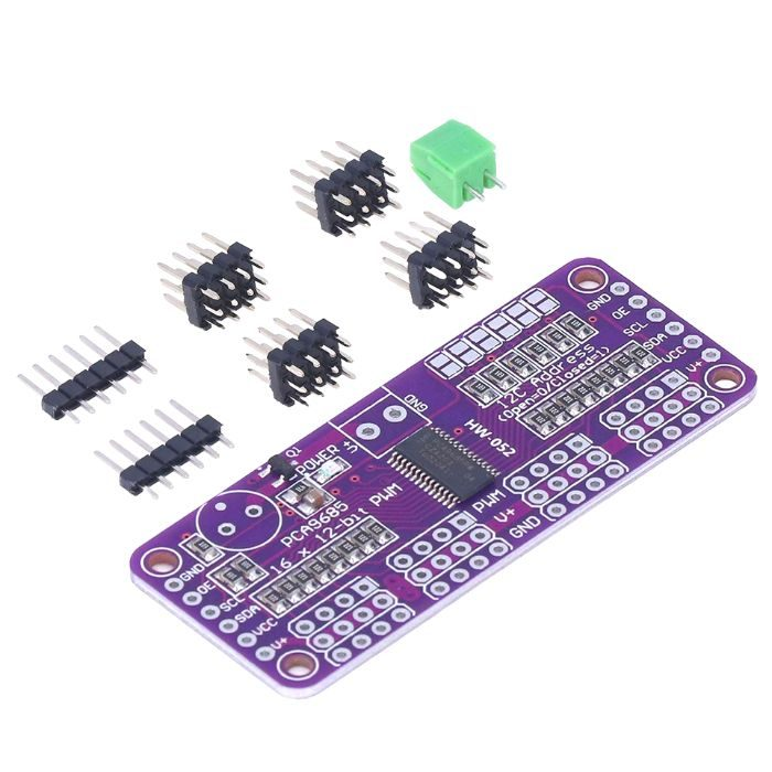
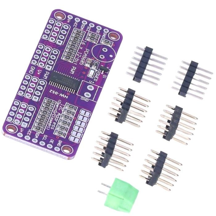
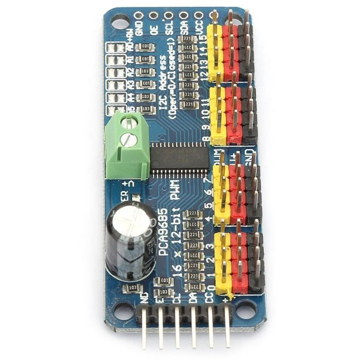
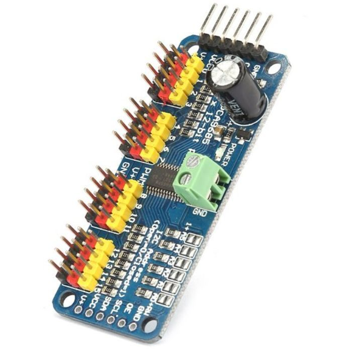
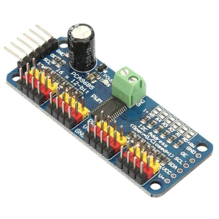
PCA9685 16 Channel Servo Motor Driver(Soldered)
This is 16-Channel 12-bit PWM/Servo Driver – I2C interface – PCA9685. You want to make a cool robot, maybe a hexapod walker, or maybe just a piece of art with a lot of moving parts. Or maybe you want to drive a lot of LEDs with precise PWM output. Then you realize that your microcontroller has a limited number of PWM outputs! What now? You could give up OR you could just get this handy PWM and Servo driver breakout.
Programmable fuzzy group (dim) / Flashing LED brightness independent mixed with 1MHz Fast-mode Plus is compatible with high drive capability has 30mA on SDA I2C bus interface to drive a highly capacitive bus. Each LED output can be achieved from the fully closed (the default) to 4096 (12) between the maximum brightness linear programmable brightness.
Software programmable open-drain LED output selection (the default is a push-pull) of 16 push-pull outputs (at 5V 25mA sink can absorb and provide 10mA current draw), no input function. Programmable output state is in response to an order to change or stop to achieve simultaneously update all outputs or by-byte (byte-by-byte) update output (default is “Stop command to change”). Effective low output enable input pin when the pin is high, the LED output can be programmed to 0,1 or tri-state (high impedance power-on default).
6 hardware address pins so that the same can be connected to 62 PCA9685 I2C devices on the bus. LED output frequency (all LED) is typically 40Hz to 1000Hz (When the oscillator is 25MHz, the prescaler register default value 1EH 200Hz refresh rate will generate a). 4 software programmable I2C bus address (an LED group call (Call) address and three sub-LED call (Call) address) such that the device can be set in any combination to be addressed at the same time (e.g., a register used for ” All calls (All Call) “then all PCA9634 devices on the I2C bus can be addressed at the same time, while the second register for three different addresses, then a device group. 1/3 bus devices can be addressed at the same time), you can enable and disable the software I2C bus address.
If you want to control the
servo motors
with this 16-channel servo motor driver, for that you will need a few essential components like
Arduino
,
jumper wires
,
batteries or power supply
.
Connection diagram for interfacing 16-Channel 12-bit PWM/Servo Driver – I2C interface – PCA9685 with Arduino UNO:
Features:
Adjustable frequency PWM up to about 1.6 KHz
Configurable push-pull or an open-drain output
The output enable pin to quickly disable all the outputs
Reverse polarity protection on the terminal block input
3 pin connectors in groups of 4 so you can plug in 16 servos at once
Terminal block for power input
Also check the
PCA9685 16 Channel 12 Bit Servo Motor Driver
available on the Iotcart website. The driver offers adjustable frequency PWM up to 1.6 KHz, 12-bit resolution for each output, and supports configurable push-pull or open-drain output. It has an output enable pin to disable all outputs, reverse polarity protection, and a green power-good LED.
₹243,69
MRP. ₹628,60
Incl. GST (No Hidden Charges)
Incl. GST (No Hidden Charges)
PCA9685 16 Channel Servo Motor Driver(Soldered)
PCA9685 16 Channel Servo Motor Driver(Soldered) This is 16-Channel 12-bit PWM/Servo Driver – I2C interface – PCA9685. You want to make a cool robot, maybe a hexapod walker, or maybe …
As low as
₹243,69
₹243,69
MRP. ₹628,60
Incl. GST (No Hidden Charges)
