

Sort by
KK board 2.1.5 Multi-Rotor LC…
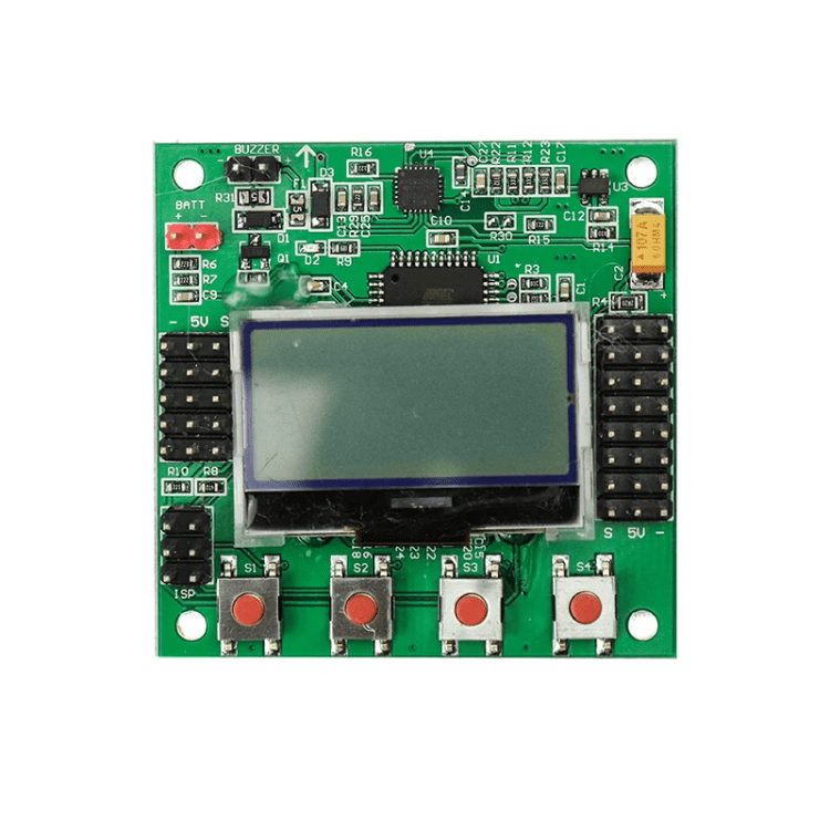
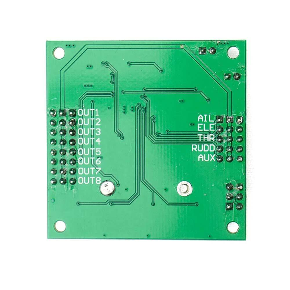
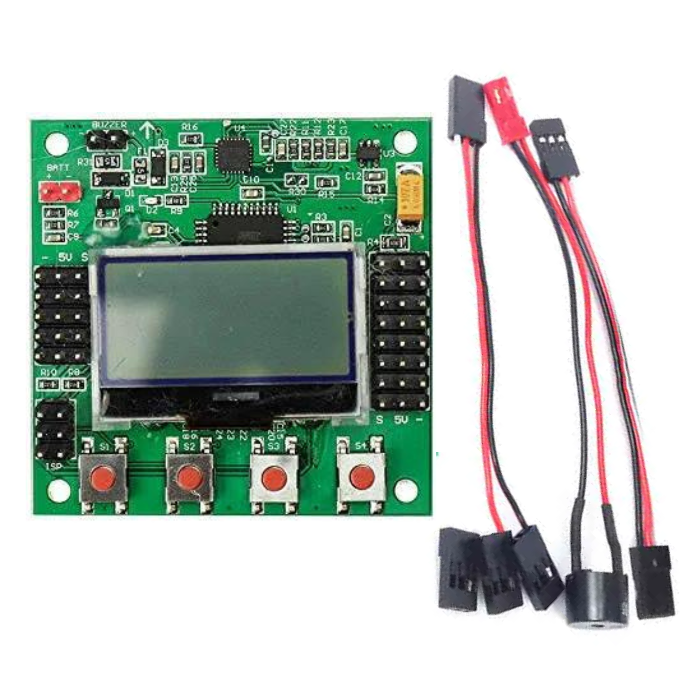
KK board 2.1.5 Multi-Rotor LCD Flight Control Board
The KK 2.1.5 Flight controller board is a highly efficient flight controller for drones that is designed to manage the flight of various multi-rotor aircraft, such as Tricopters, Quadcopters or
drones
, and Hexacopters.
Its primary function is to stabilize the aircraft during flight by taking signals from onboard gyroscopes for roll, pitch, and yaw, and passing them to the Atmega324PA processor.
The processor then processes the signals according to the user's firmware selection and sends the control signals to the
Electronic Speed Controllers (ESCs)
, making it one of the best flight controllers for drones.
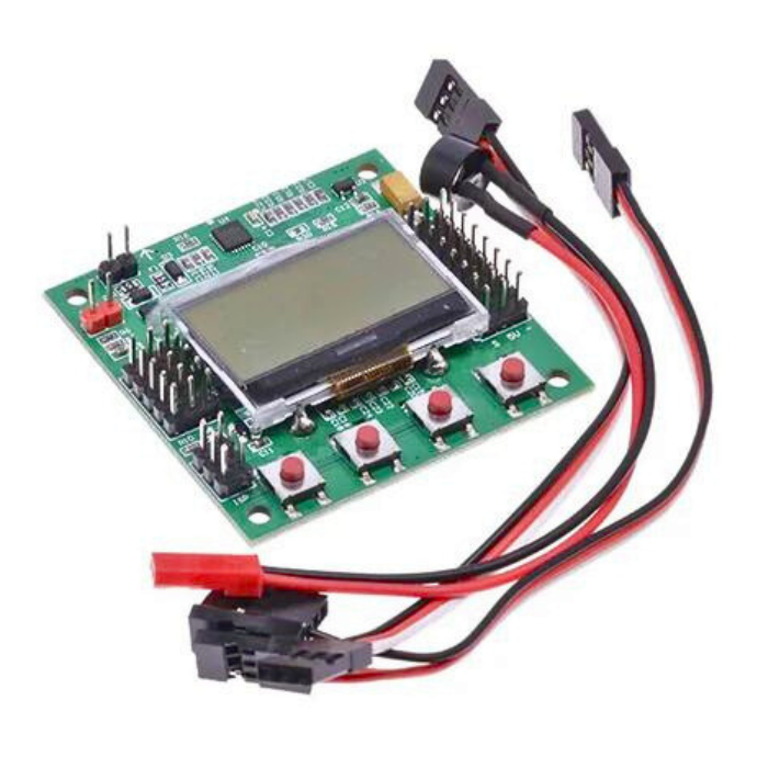
The KK2.1.5 board receives signals from the radio system via a receiver and passes these signals along with stabilization signals to the Atmega324PA IC via aileron, elevator, throttle, and rudder user demand inputs.
This information is then processed and sent to the ESCs, which adjust the rotational speed of each motor to control flight orientation, making it an excellent
flight controller
for drone enthusiasts.
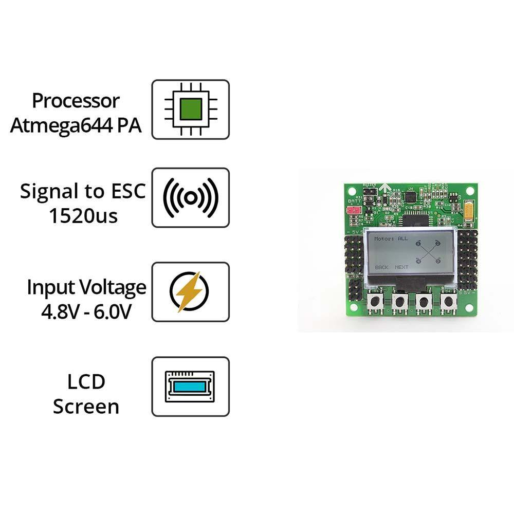
The kk2.1.5 flight controller board is designed with the beginner in mind, with a sensitive MPU 6050 gyro system that allows for the addition of an auto-level function.
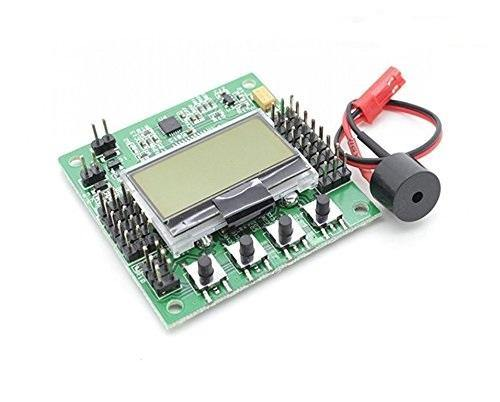
It also features an ATMEL Mega 644PA 8-bit AVR RISC-based microcontroller with 64k of memory, as well as a voltage detection header and a piezo buzzer for audio warning when activating or deactivating the board, making it one of the best flight controllers for drones available on the market.
Additionally, the board includes a 6-pin USBasp AVR programming interface for easy software updates, making the kk flight controller board an ideal choice for those looking for the best flight controller for drones.
How To Set Up KK 2.1.5 Flight Controller
For those unsure of how to set up a KK Flight Control board, the KK2.1 Flight Control Board is the perfect solution, offering pre-installed firmware for a variety of multi-rotor craft types.
Simply select your aircraft type, motor layout, and propeller direction, calibrate your ESCs and radio, and follow the on-screen prompts for easy set-up.
Also check our
flight controller for drone
collection, features a variety of drone flight controllers, including popular models.
Features
Most stable KK Board ever.
6050 MPU system based.
Easy graphical interfacing with the receiver.
In Built firmware.
Easy to use for beginners.
Applications:
Quadcopter Stabilizer
Multirotor Aircraft Flight Controller
₹4276,26
MRP. ₹7698,60
Incl. GST (No Hidden Charges)
Incl. GST (No Hidden Charges)


KK board 2.1.5 Multi-Rotor LCD Flight Control Board
KK board 2.1.5 Multi-Rotor LCD Flight Control Board The KK 2.1.5 Flight controller board is a highly efficient flight controller for drones that is designed to manage the flight of …
As low as
₹4276,26
₹4276,26
MRP. ₹7698,60
Incl. GST (No Hidden Charges)
KY-010 Broken Light Blocking …
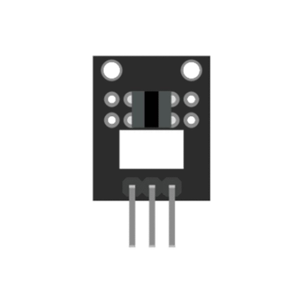
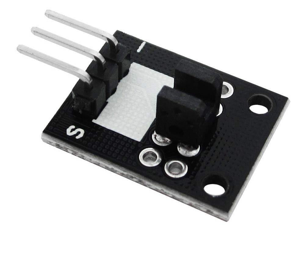
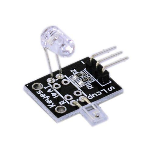
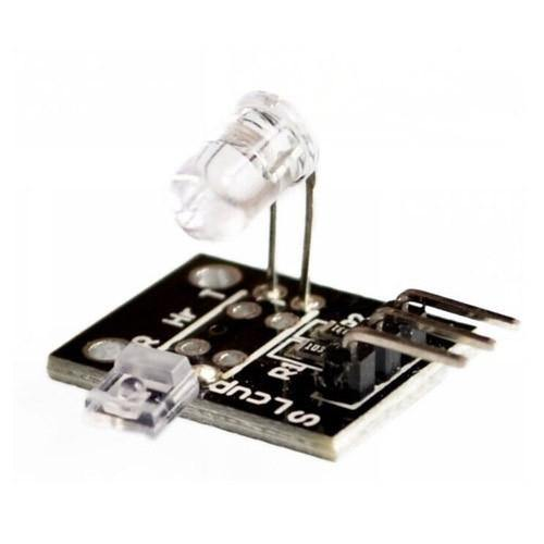
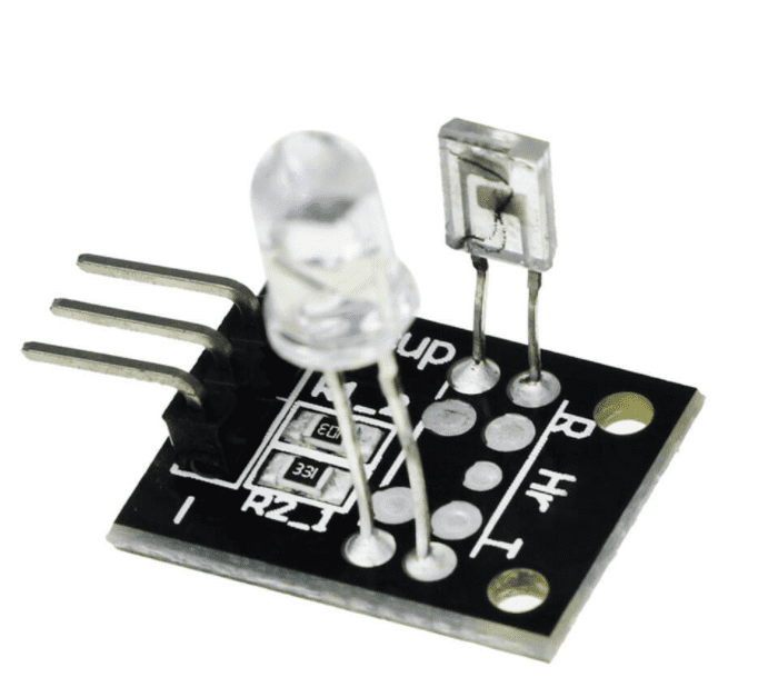
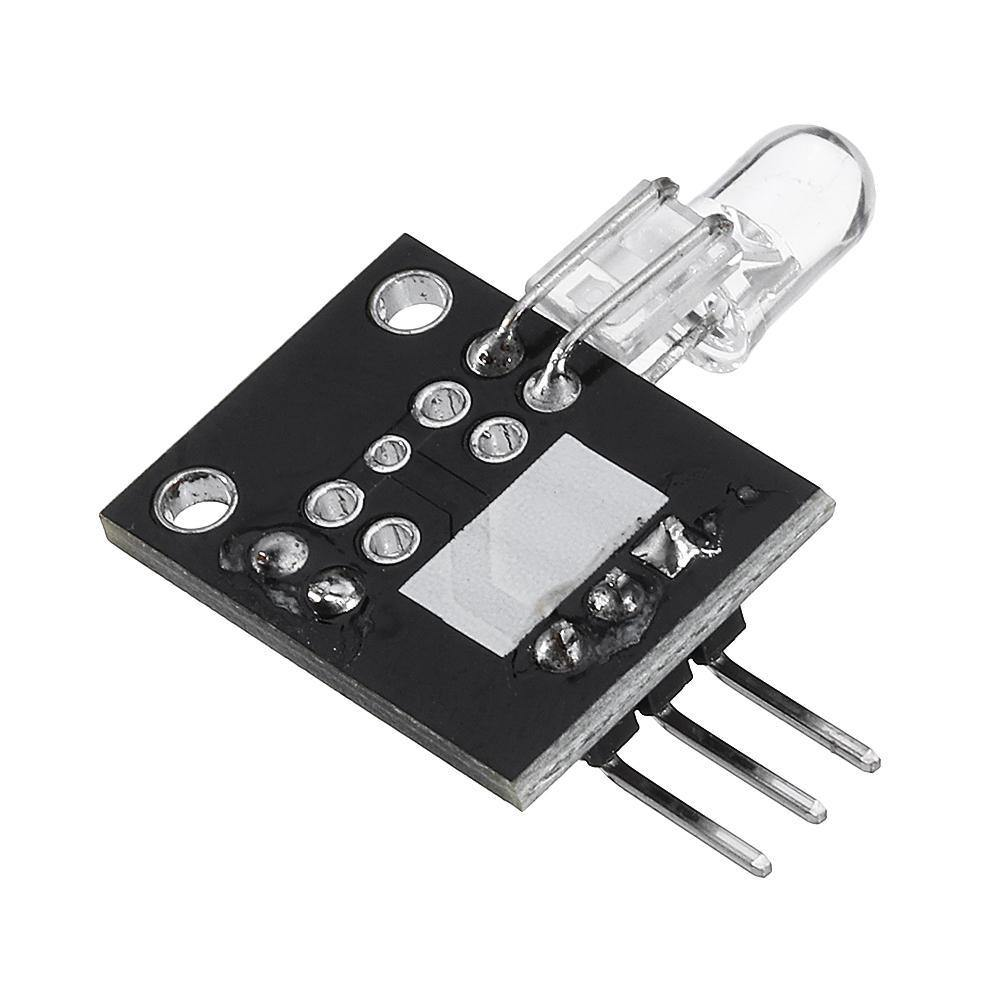
Y-010 Broken Light Blocking Sensor
The KY-010 Photo Interrupter module consists of an optical emitter/detector in the front and two resistors (1 k? and 33 ?) in the back. The sensor uses a beam of light between de emitter an detector to check if the path between both is being blocked by an opaque object.
KY010 Sensor Connection Diagram
Connect the power line (middle) and ground (left) to +5V and GND respectively. Connect signal (S) to pin 3 on the Arduino.
- (left)
GND
middle
+5V
S (right)
Pin 3
₹44,51
MRP. ₹75,60
Incl. GST (No Hidden Charges)
Incl. GST (No Hidden Charges)
KY-010 Broken Light Blocking Sensor
Y-010 Broken Light Blocking Sensor The KY-010 Photo Interrupter module consists of an optical emitter/detector in the front and two resistors (1 k? and 33 ?) in the back. The …
As low as
₹44,51
₹44,51
MRP. ₹75,60
Incl. GST (No Hidden Charges)
KY-036 Metal Touch Sensor
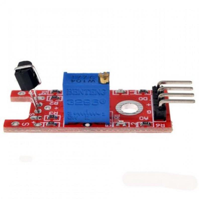
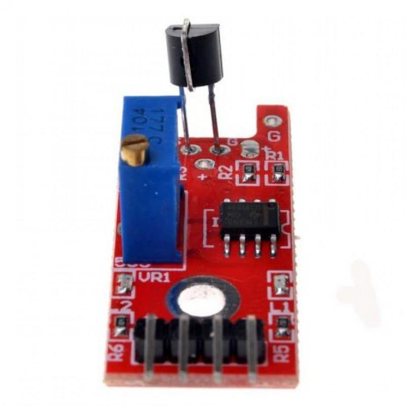
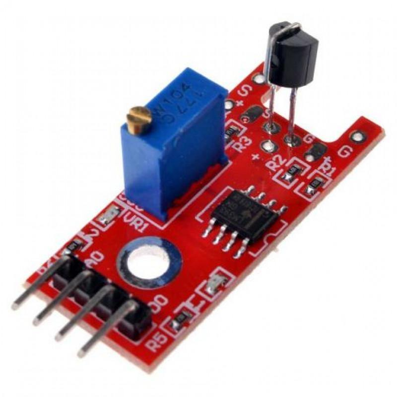
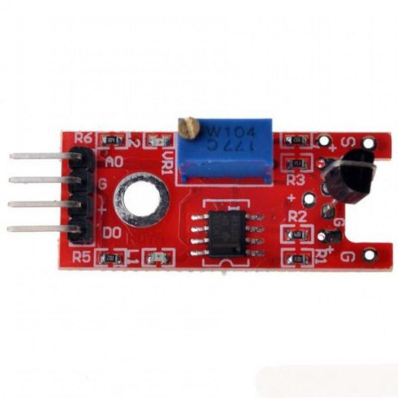
KY-036 Metal Touch Sensor
The KY-036
Touch Sensor
Module utilizes a floating lead on a Darlington transistor to detect a touch. There are 2 LEDs on-board. A red LED lights when power is applied. A green or red LED lights when a touch is detected.
It's a simple module that can be easily integrated into a circuit, it can be connected to an MCU (microcontroller unit) using just three pins: VCC, GND and Signal. The signal pin goes high when the sensor is touched and goes low when the touch is removed. It can be used in a variety of applications where touch sensing is required such as buttons, touchscreens, and other human-machine interfaces.
₹48,96
MRP. ₹96,60
Incl. GST (No Hidden Charges)
Incl. GST (No Hidden Charges)
KY-036 Metal Touch Sensor
KY-036 Metal Touch Sensor The KY-036 Touch Sensor Module utilizes a floating lead on a Darlington transistor to detect a touch. There are 2 LEDs on-board. A red LED lights …
As low as
₹48,96
₹48,96
MRP. ₹96,60
Incl. GST (No Hidden Charges)
KY-039 Finger Heartbeat Detec…
KY-039 Finger Heartbeat Detection Sensor
The KY-039 Finger Heartbeat Detection Sensor is a sensor that can detect a person's pulse or heartbeat. It is a small, portable
sensor
that easily connects to an Arduino or other microcontroller to read and analyse heart rate. The sensor is made up of a finger clip that attaches to the finger and an infrared sensor that detects blood flow through the finger. The sensor sends information to the microcontroller, which computes the heart rate. The sensor generates an analogue output signal that the microcontroller can read.
The LED is on the light side of the finger, and the phototransistor is on the other side of the finger, the phototransistor is used to obtain the flux emitted when the blood pressure pulse by the finger when the resistance of the phototransistor will be slightly changed.
We chose a very high resistance resistor R1 because most of the light through the finger is absorbed, it is a desirable phototransistor sensitive enough.
The most important is to keep the shield stray light into the phototransistor. For home lighting that is particularly important because the lights at home are mostly based on 50HZ or 60HZ fluctuating, so a faint heartbeat will add considerable noise.
Applications:
DIY Heart Rate Sensor
Heart Rate Monitor Using IoT
MAX 30102 Heart Rate Monitor on 16x2 LCD
₹34,49
Incl. GST (No Hidden Charges)
Out of Stock
MRP. ₹61,60
Incl. GST (No Hidden Charges)
KY-039 Finger Heartbeat Detection Sensor
KY-039 Finger Heartbeat Detection Sensor The KY-039 Finger Heartbeat Detection Sensor is a sensor that can detect a person's pulse or heartbeat. It is a small, portable sensor that easily …
As low as
₹34,49
₹34,49
MRP. ₹61,60
Incl. GST (No Hidden Charges)
Out of Stock
KY033 TCRT5000 Sensor
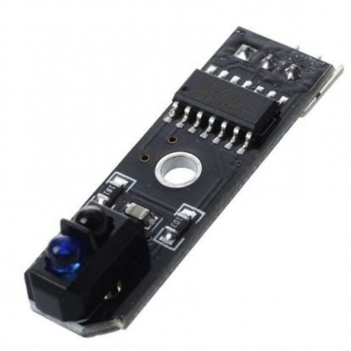
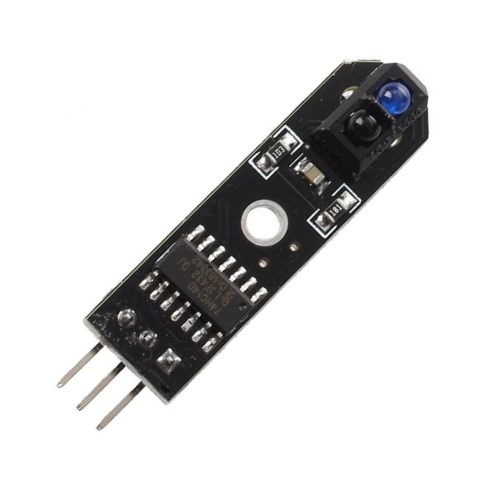
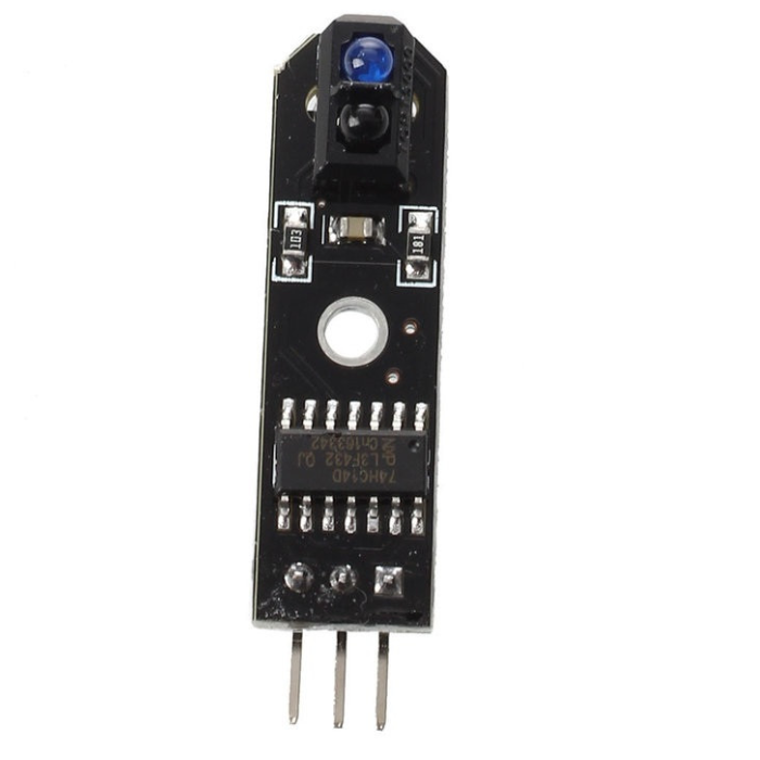
KY033 TCRT5000 Sensor
The TCRT5000 Single Channel Line Tracking Sensor Module is a great detector for a
line-following robot
. Potentiometer to adjust the sensitivity of the individual sensors.
TCRT5000 infrared sensor emits infrared emitting diode continuously when no infrared rays emitted or reflected back is reflected back but the strength is not large enough, the phototransistor has been in the off state, and the output terminal of the module is high, indicating that the diode has been in the off state; in the object to be detected within the detection range, and the intensity of the reflected infrared rays is large enough, phototransistor saturated, and the output terminal of the module is low, the indicator LED is lit.
TCRT5000 Single Channel Line Tracking
Sensor Module
is a carrier board for the TCRT5000 reflective optical sensor. Although it is designed for use with line-following robots, it can be used in mini-sumo robots for line control. The board has a digital output.
Applications:
Position sensor for shaft encoder
Detection of reflective material such as paper, IBM cards, magnetic tapes etc.
Limit switch for mechanical motions in VCR
General purpose - wherever the space is limited
₹41,17
MRP. ₹81,20
Incl. GST (No Hidden Charges)
Incl. GST (No Hidden Charges)
KY033 TCRT5000 Sensor
KY033 TCRT5000 Sensor The TCRT5000 Single Channel Line Tracking Sensor Module is a great detector for a line-following robot . Potentiometer to adjust the sensitivity of the individual sensors. TCRT5000 …
As low as
₹41,17
₹41,17
MRP. ₹81,20
Incl. GST (No Hidden Charges)
L Clamp For Mounting Geared M…
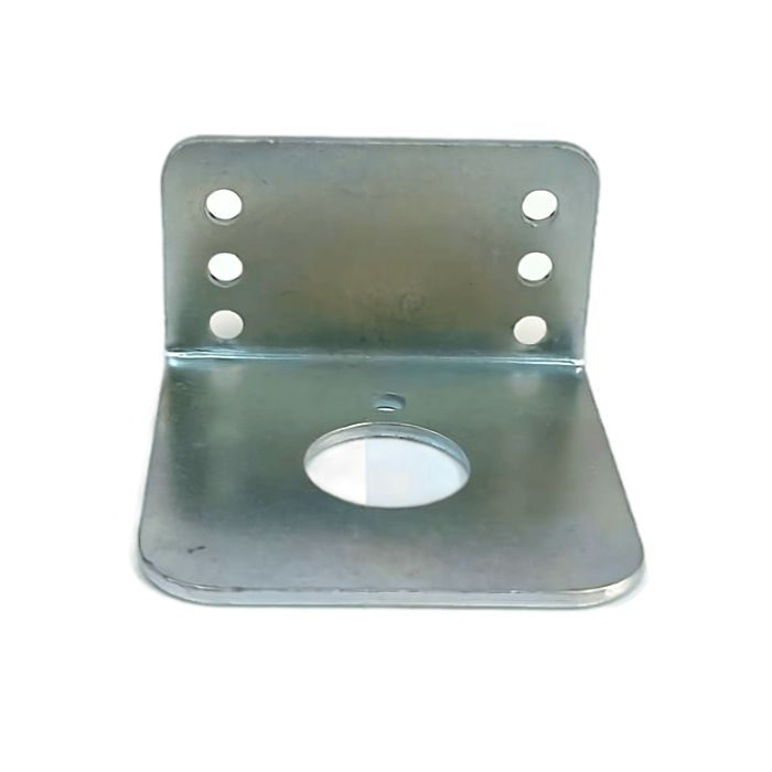
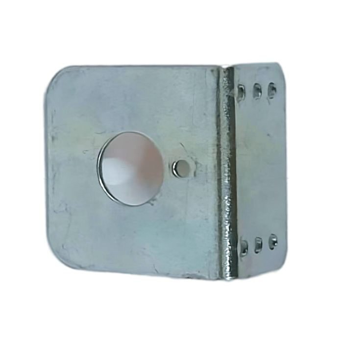
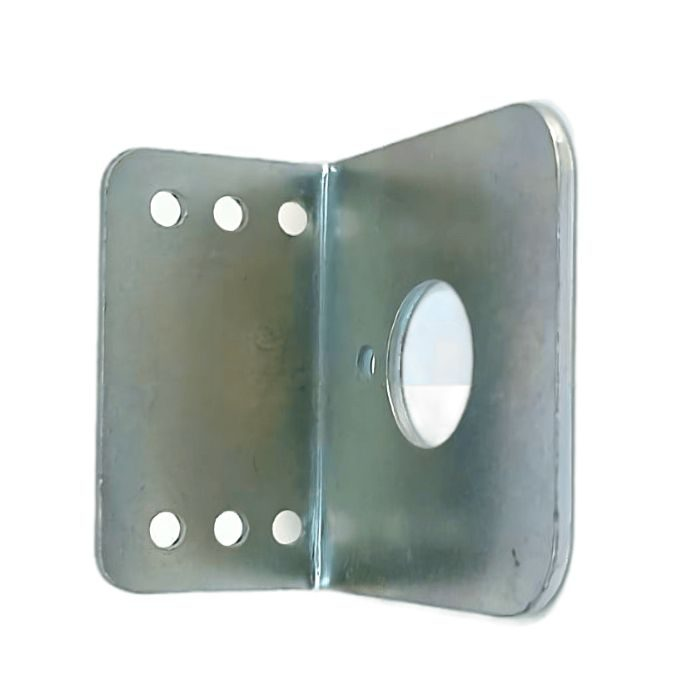
L Clamp For Mounting Geared Motor
L-clamp for Mounting Geared Motor is a high-quality, easy to install motor clamp that offers reliable and lasting performance. This versatile motor clamp is designed specifically for mounting geared motors securely on boards or other surfaces providing superior holding capability with minimal effort.
Its rustproof zinc alloy construction ensures long life while its tight seal prevents any leakage of oil during operation due to temperature fluctuations in the environment. The product has been tested extensively against tough environmental conditions such as extreme weather changes and vibration shocks from machinery operations ensuring the highest levels of efficiency at all times.
This motor clamp is ideal for engineers who need accuracy when installing gears into their projects regularly without prior experience in electronics engineering, this motor mount will make your job easier than ever preventing fatigue while performing complex tasks quickly and accurately every single time, delivering exceptional value right away!
check out :
BO MOTOR CLAMP (PACK OF 5)
Features:
Suitable for Center Shaft Gear Motor
Easy installation for convenient motor mounting
Sturdy and durable construction for stability
Rustproof zinc alloy ensures long life
Designed for robotics enthusiasts and mechanical projects
Compatible Motors
200 RPM GEARED MOTOR
300 RPM GEARED MOTOR
10 RPM GEARED MOTOR
60 RPM GEARED MOTOR
Applications:
Ideal for securely mounting geared motors on boards or surfaces
Provides superior holding capability for geared motors
Suitable for use in robotics projects
₹26,70
MRP. ₹40,60
Incl. GST (No Hidden Charges)
Incl. GST (No Hidden Charges)
L Clamp For Mounting Geared Motor
L Clamp For Mounting Geared Motor L-clamp for Mounting Geared Motor is a high-quality, easy to install motor clamp that offers reliable and lasting performance. This versatile motor clamp is …
As low as
₹26,70
₹26,70
MRP. ₹40,60
Incl. GST (No Hidden Charges)
L293D 4 Channel DC Motor Driv…
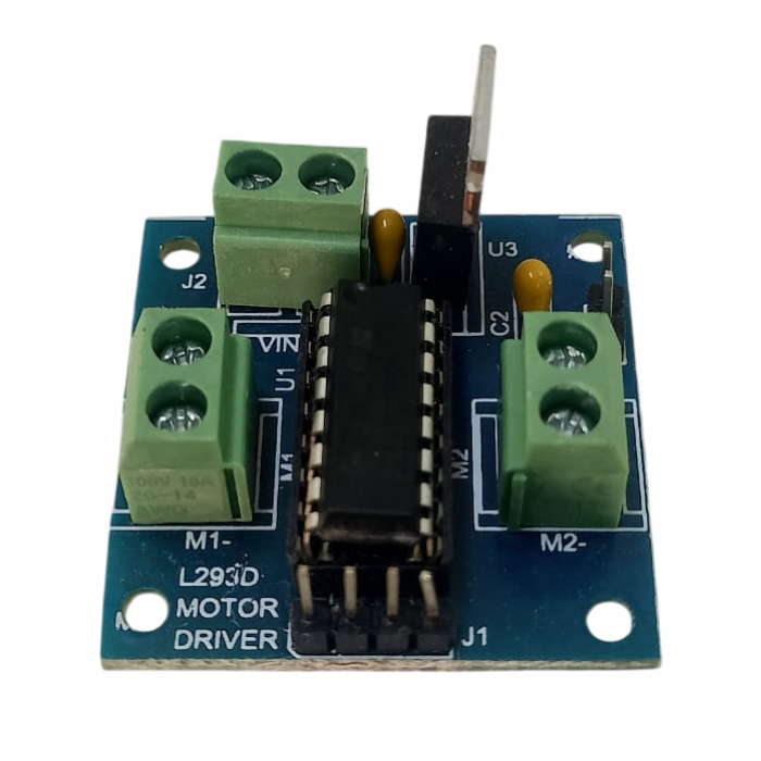
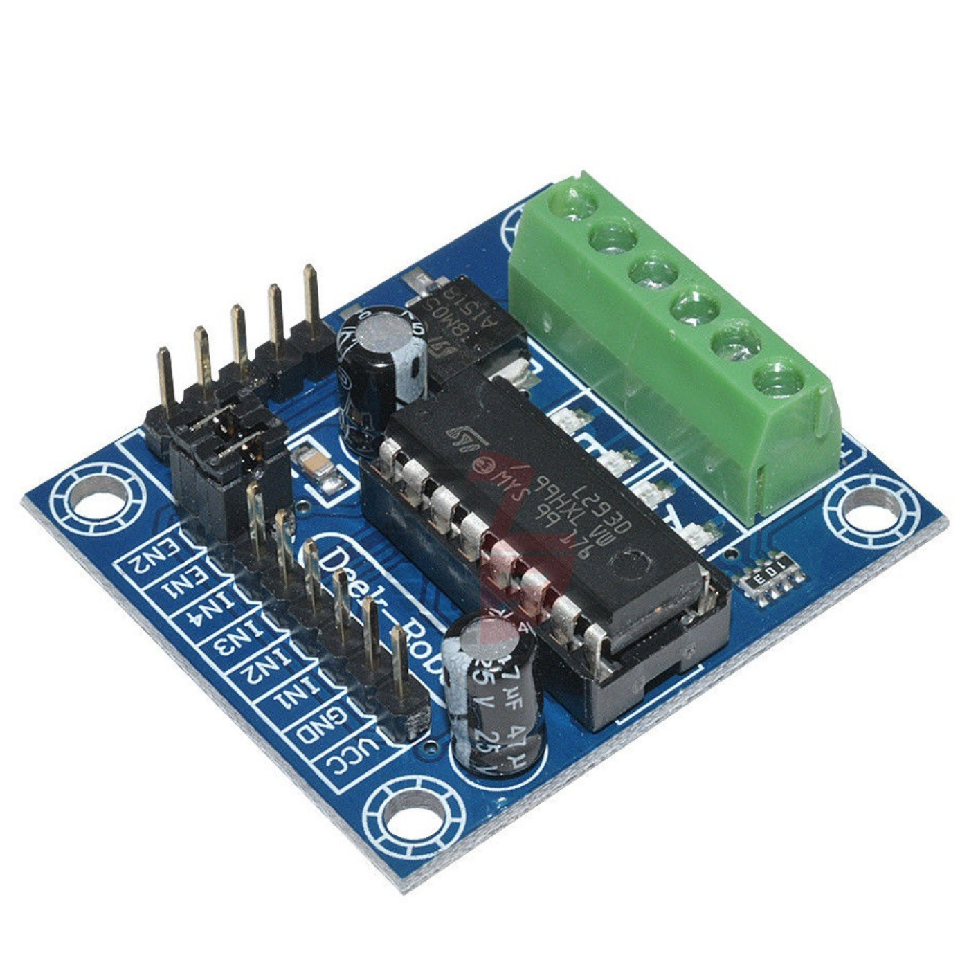
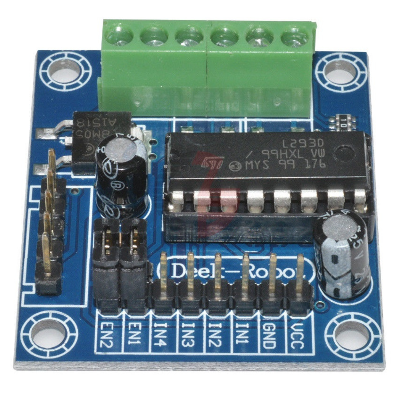
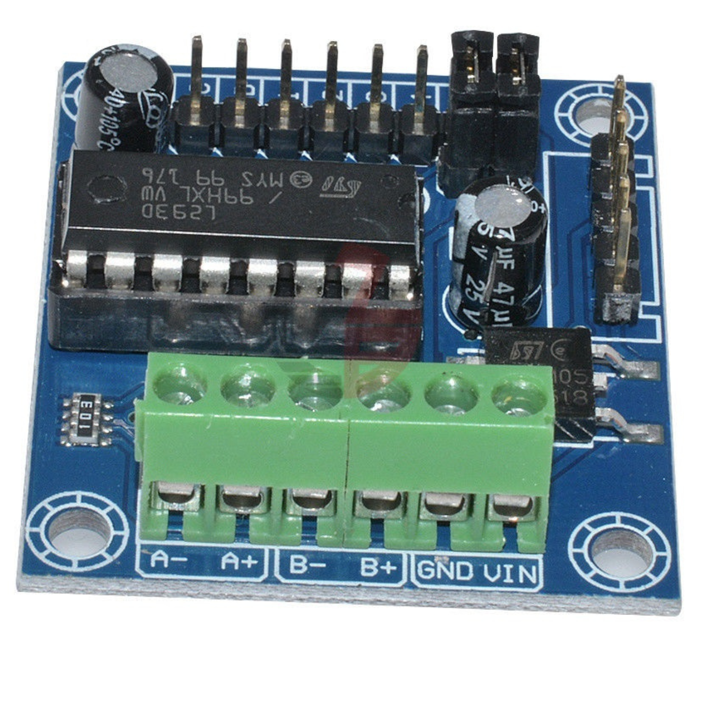
L293D 4 Channel DC Motor Driver
Motor Drive Board L293D Module For
Arduino
UNO MEGA 2560 is a Device is a monolithic integrated high voltage, high current four channel driver designed to accept standard DTL or TTL logic levels and drive inductive loads (such as relays
solenoids, DC, and stepper motors
) and switching power transistors.
To simplify use as two bridges each pair of channels is equipped with an enable input. A separate supply input is provided for the logic, allowing operation at a lower voltage, and internal clamp diodes are included. This device is suitable for use in switching applications at frequencies up to 5 kHz.
It is a medium-power motor driver perfect for driving DC Motors and Stepper Motors. It uses the popular L293 motor driver IC. It can drive 4 DC motors on and off, or drive 2 DC motors with directional and speed control. L293D DC Motor Driver Module is fully compatible with Arduino and Raspberry Pi cards. Allows you to control 2 DC motors in 2 directions at the same time. L293D DC Motor Driver has become easy to use by being turned into a module. You can integrate them into your circuits very quickly by making the necessary connections to the output and input pins.
check out :
L9110S H Bridge Stepper Motor Dual DC Driver Controller Module For Arduino
Applications:
Can be used to control motors of DIY Robot
Can be used to control motor speed and direction
Also, read our blog
What is Motor Driver
detailing an overview of motor drivers, including the different types available and how they work.
₹89,02
MRP. ₹166,60
Incl. GST (No Hidden Charges)
Incl. GST (No Hidden Charges)
L293D 4 Channel DC Motor Driver
L293D 4 Channel DC Motor Driver Motor Drive Board L293D Module For Arduino UNO MEGA 2560 is a Device is a monolithic integrated high voltage, high current four channel driver …
As low as
₹89,02
₹89,02
MRP. ₹166,60
Incl. GST (No Hidden Charges)
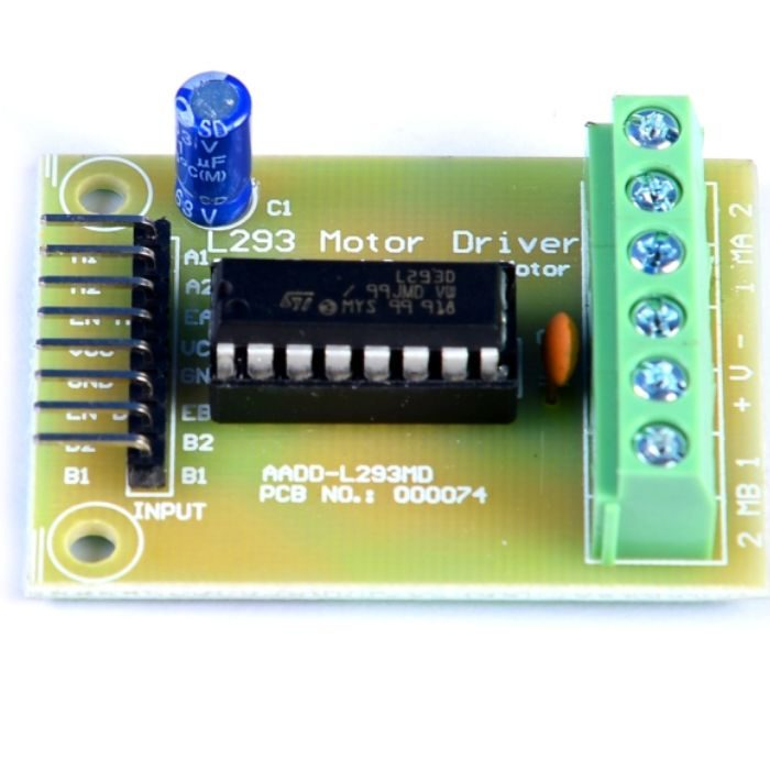
L293D Motor Driver Board
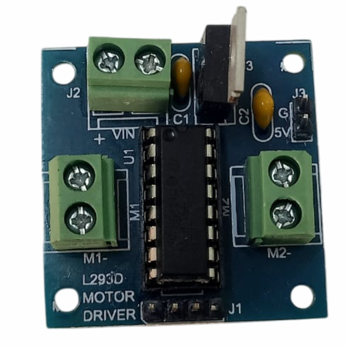
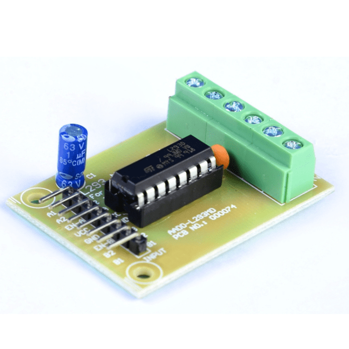
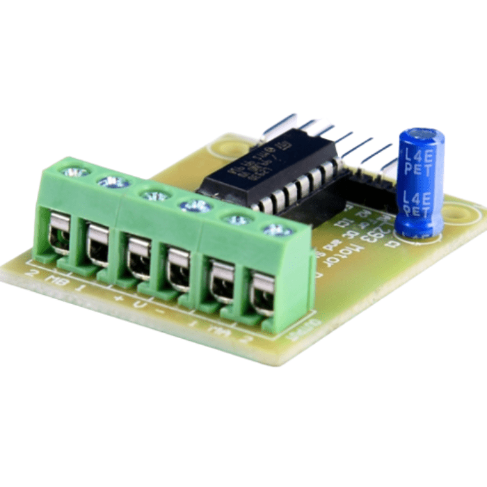
L293D Motor Driver Board
The L293D Motor Driver Module is a medium-power motor driver that is ideal for driving DC and
stepper motors
. It employs the well-known L293 motor driver IC. The l293d motor driver board can turn on and off four DC motors or control two DC motors with directional and speed control. The driver greatly simplifies and improves the ease with which microcontrollers can control motors, relays, and other devices. It has a total DC current of up to 600mA and can drive motors up to 12V.
To double the maximum current, connect the two channels in parallel, or in series to double the maximum input voltage. This motor driver is ideal for robotics and mechatronics projects that require controlling motors from microcontrollers, switches, relays, and other devices. Ideal for driving DC and Stepper motors in micro-mouse, line-following robots, robot arms, and other applications.
If you want to control the
motor
with this motor driver, for that you will need a few essential components like
Arduino
jumper wires
batteries or power supply
Features:
Pin compatible with L293D
Wide supply voltage: 4.5 V to 12 V.
Max supply current: 600 mA per motor.
The driver has two holes of 3 mm dia.
Male burg-stick connectors for supply, ground, and input connection.
Screw terminal connectors for easy motor connection.
High noise immunity inputs.
Internal ESD Protection.
Thermal Shutdown
check out :
Dual Monster Moto Shield VNH3ASP30 DC Motor Drive
₹71,21
MRP. ₹131,60
Incl. GST (No Hidden Charges)
Incl. GST (No Hidden Charges)
L293D Motor Driver Board
L293D Motor Driver Board The L293D Motor Driver Module is a medium-power motor driver that is ideal for driving DC and stepper motors . It employs the well-known L293 motor …
As low as
₹71,21
₹71,21
MRP. ₹131,60
Incl. GST (No Hidden Charges)
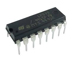
L293D Motor Driver IC
L293D Motor Driver IC
L293D IC generally comes as a standard 16-pin DIP (dual-in-line package). This
motor driver IC
can simultaneously control two small motors in either direction; forward and reverse with just 4 microcontroller pins (if you do not use enable pins).
Each chip contains two full H-bridges (four half H-bridges). That means you can drive four solenoids, two DC motors bi-directionally, or one stepper motor.
A motor driver is basically a current amplifier that takes a low-current signal from the microcontroller and gives out a proportionally higher current signal which can control and drive a motor. In most cases, a transistor can act as a switch and perform this task which drives the motor in a single direction.
Turning a motor ON and OFF requires only one switch to control a single motor in a single direction.
L293D IC generally comes as a standard 16-pin DIP (dual-in-line package). This motor driver IC can simultaneously control two small motors in either direction; forward and reverse with just 4 microcontroller pins (if you do not use enable pins).
Each chip contains two full H-bridges (four half H-bridges). That means you can drive four solenoids, two DC motors bi-directionally, or one stepper motor.
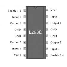
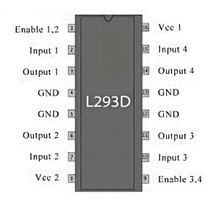
Pinout:
Pinout of L293D Motor Driver IC
Applications:
High Current Motor Driver IC.
Dual H-bridge for controlling up to two motors at a time.
Ideal for Inductive load decoupling from the main/control unit.
A wide voltage range allows for an adaptive voltage range control.
₹28,93
MRP. ₹47,60
Incl. GST (No Hidden Charges)
Incl. GST (No Hidden Charges)
L293D Motor Driver IC
L293D Motor Driver IC L293D IC generally comes as a standard 16-pin DIP (dual-in-line package). This motor driver IC can simultaneously control two small motors in either direction; forward and …
As low as
₹28,93
₹28,93
MRP. ₹47,60
Incl. GST (No Hidden Charges)
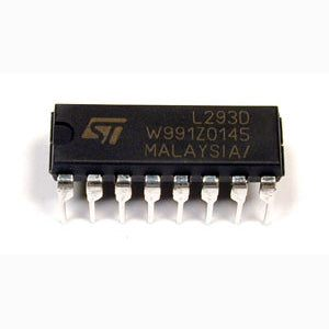
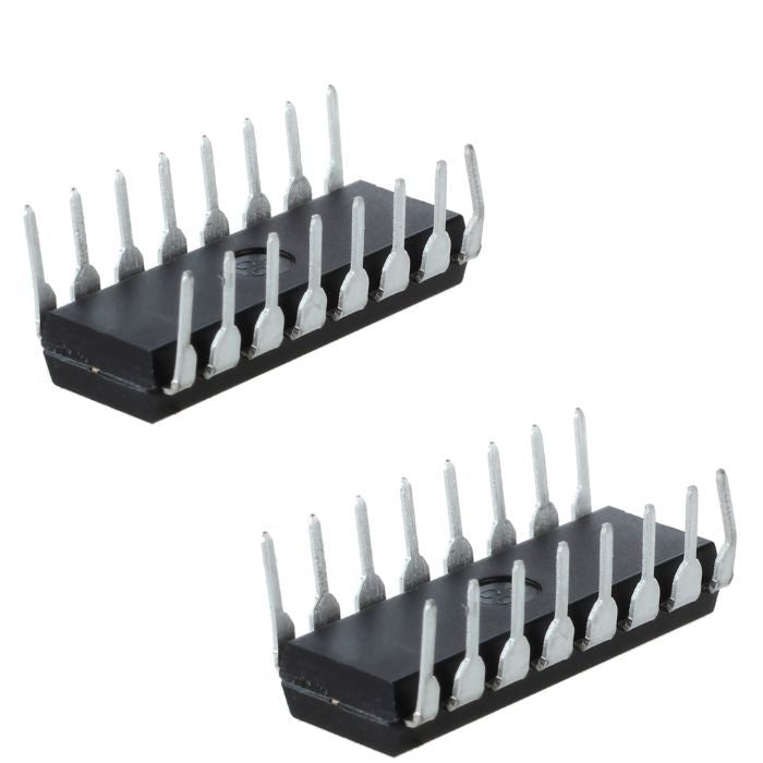
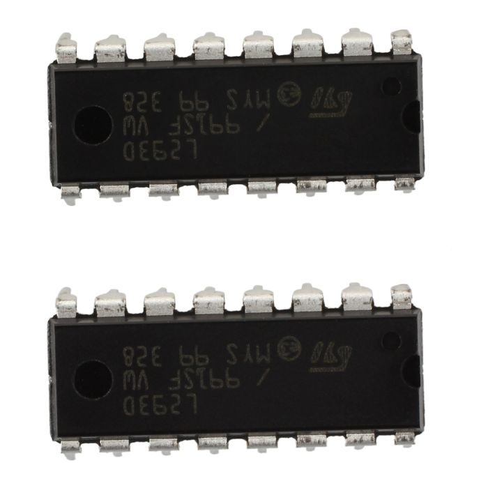
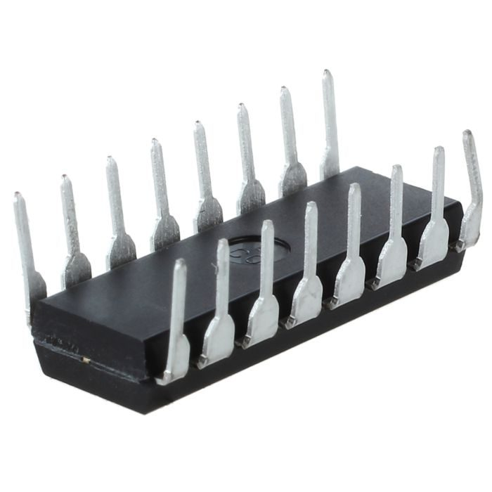
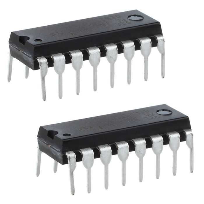
L293D Motor Driver IC (2 Pcs)
L293D Motor Driver IC (2 Pcs)
L293D PowerDIP-16 Stepper
Motor Controller/ Driver
is a dual H-bridge motor driver integrated circuit (IC). Motor drivers act as current amplifiers since they take a low-current control signal and provide a higher-current signal. This higher current signal is used to drive the motors.
The Device is a monolithic integrated high voltage, high current four channel driver designed to accept standard DTL or TTL logic levels and drive inductive loads (such as relays solenoids, DC and stepping motors) and switching power transistors. To simplify use as two bridges each pair of channels is equipped with an enable input. A separate supply input is provided for the logic, allowing operation at a lower voltage and internal clamp diodes are included.
It is suitable for use in switching applications at frequencies up to 5 kHz. The L293D is assembled in a 16 lead plastic package which has 4 centre pins connected together and used for heatsinking The L293DD is assembled in a 20 lead surface mount which has 8 centre pins connected together and used for heatsinking.
L293D contains two inbuilt H-bridge driver circuits. In its common mode of operation, two DC motors can be driven simultaneously, both in forward and reverse direction. The motor operations of two motors can be controlled by input logic at pins 2 & 7 and 10 & 15. Input logic 00 or 11 will stop the corresponding motor. Logic 01 and 10 will rotate it in clockwise and anticlockwise directions, respectively. Enable pins 1 and 9 (corresponding to the two motors) must be high for motors to start operating.
When an enable input is high, the associated driver gets enabled. As a result, the outputs become active and work in phase with their inputs. Similarly, when the enable input is low, that driver is disabled, and their outputs are off and in the high-impedance state. They are designed to drive inductive loads such as relays, solenoids, dc and bipolar stepping motors, as well as their high-current/high-voltage loads in positive-supply applications.
If you want to control the dc motor with these motor driver ICs, for that you will need few essential components like
Arduino
,
breadboard
,
jumper wires
,
batteries or power supply
.
Note: Image may vary from actual product in terms of Manufacturer/Brand name according to the availability.
Pinout:
Pinout Of L293D Motor Driver IC
Features:
Separate Input-Logic Supply
Internal ESD Protection
Thermal Shutdown
High-Noise-Immunity Inputs
Applications:
High Current Motor Driver IC.
Dual H-bridge for controlling up to two motors at a time.
Ideal for Inductive load decoupling from the main/control unit.
Wide voltage range allows for an adaptive voltage range control.
₹63,43
MRP. ₹95,20
Incl. GST (No Hidden Charges)
Incl. GST (No Hidden Charges)
L293D Motor Driver IC (2 Pcs)
L293D Motor Driver IC (2 Pcs) L293D PowerDIP-16 Stepper Motor Controller/ Driver is a dual H-bridge motor driver integrated circuit (IC). Motor drivers act as current amplifiers since they take …
As low as
₹63,43
₹63,43
MRP. ₹95,20
Incl. GST (No Hidden Charges)
