

Sort by
DPDT Switch
DPDT Switch
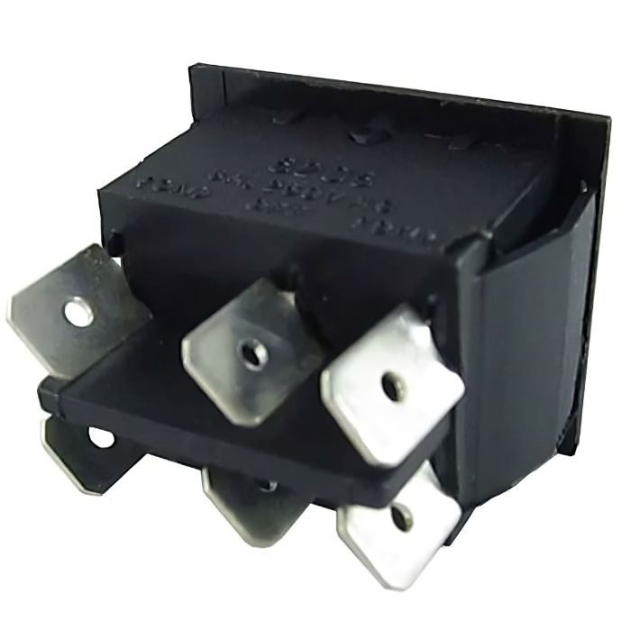
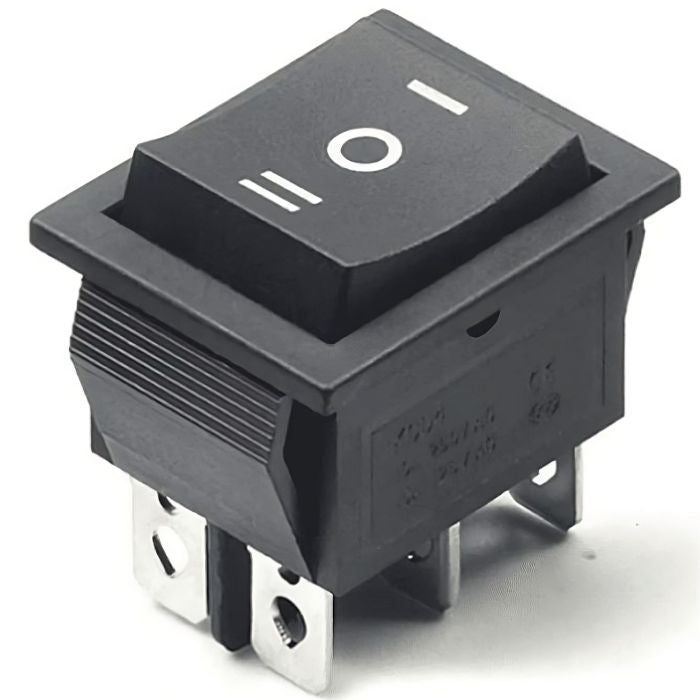
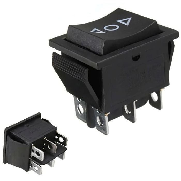
A DPDT switch or Double Pole Double Throw switch is an electromechanical switch with two inputs and four outputs, with each input having two corresponding outputs. A simple way to think of this switch is to imagine 2 SPDT switches side by side with the 'handles' attached to each other. Perhaps the most popular use for this switch is 'phase or polarity reversal'. So, how does the DPDT switch accomplish this? First, you have to wire the 2 'top' and 2 'bottom' terminals in a 'criss-cross' fashion. The top 2 terminals become the input and the middle two terminals become the output. Let pin1 is X,pin2 is Z,pin5 is Y and pin6 is W now, W & Y are connected, as are X & Z. The polarity is maintained because the input and output are directly connected When the switch is in the 'down' position. The + input goes from the 'W' terminal, down to the lower right, and then up to the 'Z' terminal. The negative input goes from the 'X' terminal and out through the 'Y' terminal. See what has happened? With one flip of a switch, polarity has been reversed.
This switch is very simple to install
electronic components
because it includes a locking system that allows you to directly lock and unlock the switch in your remote cabinet without the use of any screws or Nut-Bolts. If you want to use this switch in your projects, for that you will need a few essential components like
dc motors
,
batteries or power supply
,
bo motors
,
wires and connectors
₹42,28
MRP. ₹82,60
Incl. GST (No Hidden Charges)
Incl. GST (No Hidden Charges)
DPDT Switch
DPDT Switch A DPDT switch or Double Pole Double Throw switch is an electromechanical switch with two inputs and four outputs, with each input having two corresponding outputs. A simple …
As low as
₹42,28
₹42,28
MRP. ₹82,60
Incl. GST (No Hidden Charges)

DPDT Switch box
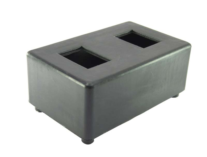
DPDT Switch Box for Robot with 2 DPDT Switch, switch box with 2 DPDT Switch
This is Robotics Switch Box Enclosure Without DPDT Switches. The switch box is used to accommodate two DPDT Rocker Switches. It is a perfect makeshift remote for your robot.
This is a Remote Control Box for Wired Hobby Robot Control. To make the anti-clockwise motion of the motor, the polarity of the supply must be inverted in a clockwise motion. For “Polarity Reversal” DPDT switches are generally used.
A Double Pole Double Throw (DPDT) switch is an electromechanical switch that has 2 inputs and 4 outputs and each input has 2 corresponding outputs that it can connect to.
Applications:
Remote-controlled robot.
AVR-based robotics projects.
ARM-based robotics projects.
PIC-based robotics projects.
Arduino-based robotics projects.
Raspberry-pi-based robotics projects.
Android-based robotic projects.
₹44,51
MRP. ₹68,60
Incl. GST (No Hidden Charges)
Incl. GST (No Hidden Charges)
DPDT Switch box
DPDT Switch Box for Robot with 2 DPDT Switch, switch box with 2 DPDT Switch This is Robotics Switch Box Enclosure Without DPDT Switches. The switch box is used to …
As low as
₹44,51
₹44,51
MRP. ₹68,60
Incl. GST (No Hidden Charges)
DS1307 Real Time Clock Module
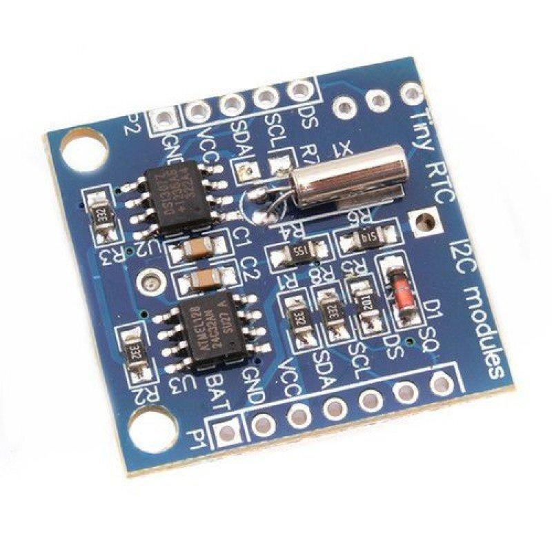
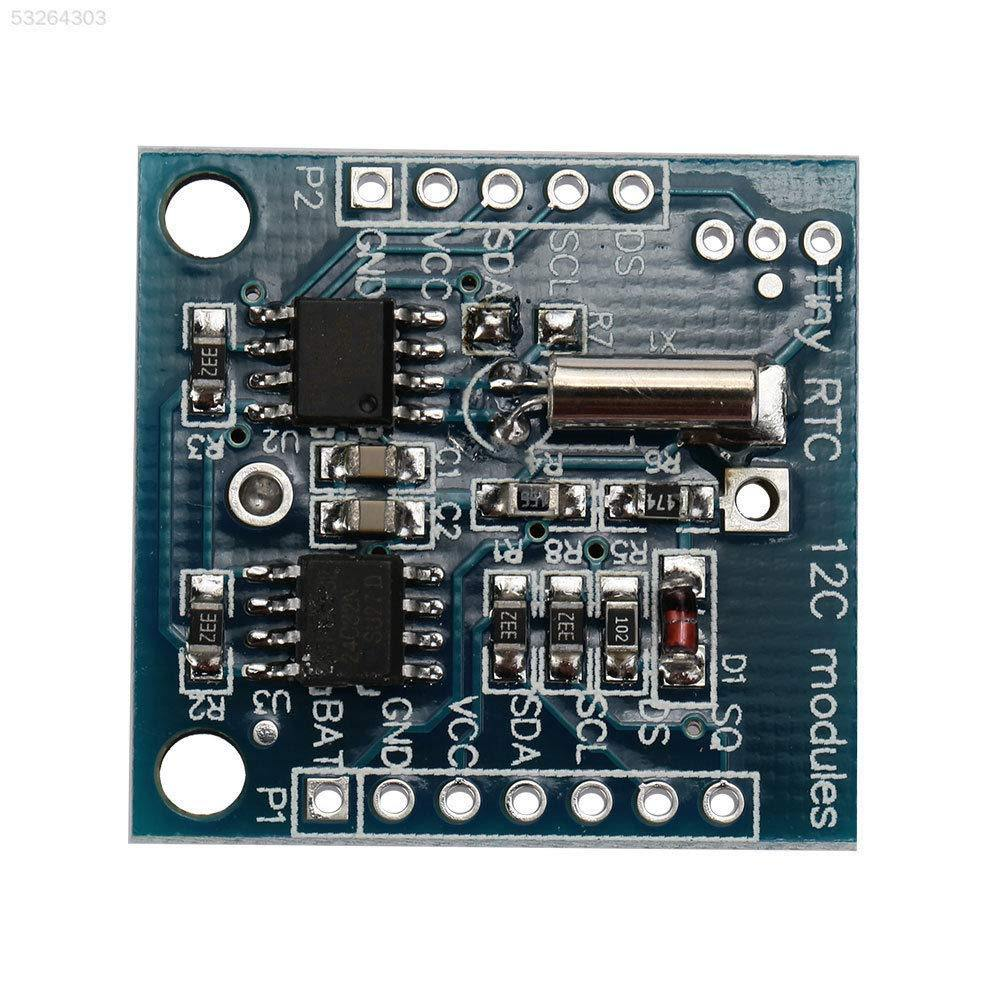
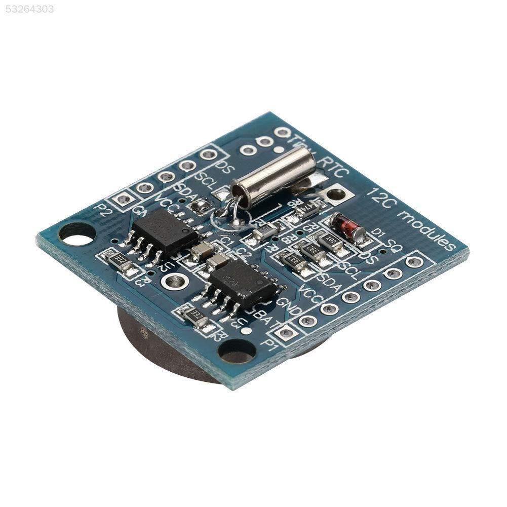
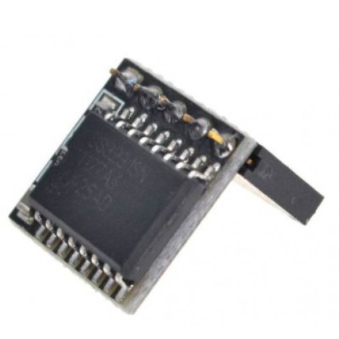
DS1307 Real Time Clock Module
The DS1307 is a low-power clock/calendar with 56 bytes of battery backup SRAM. The clock/calendar provides seconds, minutes, hours, day, date, month and year-qualified data. The end date of each month is automatically adjusted, especially for months with less than 31 days.
This is Tiny RTC Real Time Clock DS1307 I2C IIC Module for
Arduino
. It contains a DS1307
real-time clock IC
. It’s one of the easiest to use RTCs out there, with Arduino and other libraries or simply use I2C commands to set and retrieve the time and date.
Along with the DS1307 real-time clock, the module also has an Atmel 24C32 EEPROM chip which is handy for storing data without worrying about power loss. There is also space on the board to solder your own DS18B20 temperature sensor.
DS1307 Real Time Clock module is used to track the current time and date. It is generally used in computers, laptops, mobiles, embedded system applications devices, etc. In many embedded systems, we need to put timestamps while logging data i.e. sensor values, GPS coordinates, etc. For getting timestamps, we need to use RTC (Real Time Clock). This module is based on the DS1307 IC from Dallas. It uses a 32.768 kHz clock. And supports I2C Interface.
Pinout of DS1307:
Pinout of DS1307 Real Time Clock Module
Pin 1, 2:
Connections for standard 32.768 kHz quartz crystal. The internal oscillator circuitry is intended for operation with a crystal having a specified load capacitance of 12.5pF. X1 is the input to the oscillator and can alternatively be connected to an external 32.768 kHz oscillator. The output of the internal oscillator, X2 is drifted if an external oscillator is connected to X1.
Pin 3
: Battery input for any standard 3V lithium cell or another energy source. Battery voltage should be between 2V and 3.5V for suitable operation. The nominal write-protect trip point voltage at which access to the RTC and user RAM is denied is set by the internal circuitry as 1.25 x VBAT nominal. A lithium battery with 48mAhr or greater will back up the DS1307 for more than 10 years in the absence of power at 25ºC. UL is recognized to ensure against reverse charging current when utilized as part of conjunction with a lithium battery.
Pin 4:
Ground.
Pin 5:
Serial data input/output. The input/output for the I2C serial interface is the SDA, which is the open drain and requires a pull-up resistor, allowing a pull-up voltage of 5.5V. Regardless of the voltage on VCC.
Pin 6:
Serial clock input. It is the I2C interface clock input and is used in data synchronization.
Pin 7:
Square wave/output driver. When enabled, the SQWE bit set to 1, the SQW/OUT pin outputs one of four square-wave frequencies (1Hz, 4 kHz, 8 kHz, and 32 kHz). This is also an open drain and requires an external pull-up resistor. It requires the application of either Vcc or Vb at to operate SQW/OUT, with an allowable pull-up voltage of 5.5V and can be left floating, if not used.
Pin 8:
Primary power supply. When the voltage is applied within normal limits, the device is fully accessible and data can be written and read. When a backup supply is connected to the device and VCC is below VTP, read and write are inhibited. However, at low voltages, the timekeeping function still functions.
₹45,62
MRP. ₹96,60
Incl. GST (No Hidden Charges)
Incl. GST (No Hidden Charges)
DS1307 Real Time Clock Module
DS1307 Real Time Clock Module The DS1307 is a low-power clock/calendar with 56 bytes of battery backup SRAM. The clock/calendar provides seconds, minutes, hours, day, date, month and year-qualified data. …
As low as
₹45,62
₹45,62
MRP. ₹96,60
Incl. GST (No Hidden Charges)
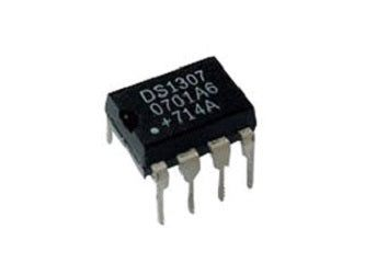
DS1307 RTC IC (Real Time Cloc…
The DS1307 serial real-time clock (RTC) is a lowpower, full binary-coded decimal (BCD) clock/calendar plus 56 bytes of NV SRAM. Address and data are transferred serially through an I2C, bidirectional bus.
The clock/calendar provides seconds, minutes, hours, day, date, month, and year information. The end of the month date is automatically adjusted for months with fewer than 31 days, including corrections for leap year. The clock operates in either the 24-hour or 12- hour format with AM/PM indicator. The DS1307 has a built-in power-sense circuit that detects power failures and automatically switches to the backup supply. Timekeeping operation continues while the part operates from the backup supply.
₹93,47
MRP. ₹176,40
Incl. GST (No Hidden Charges)
Incl. GST (No Hidden Charges)
DS1307 RTC IC (Real Time Clock)
The DS1307 serial real-time clock (RTC) is a lowpower, full binary-coded decimal (BCD) clock/calendar plus 56 bytes of NV SRAM. Address and data are transferred serially through an I2C, bidirectional …
As low as
₹93,47
₹93,47
MRP. ₹176,40
Incl. GST (No Hidden Charges)
DS3231 Real Time Clock Module…
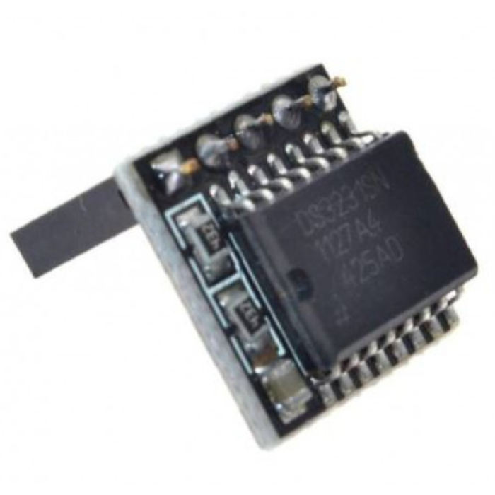
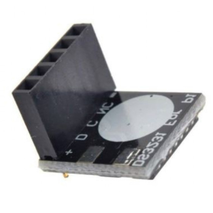
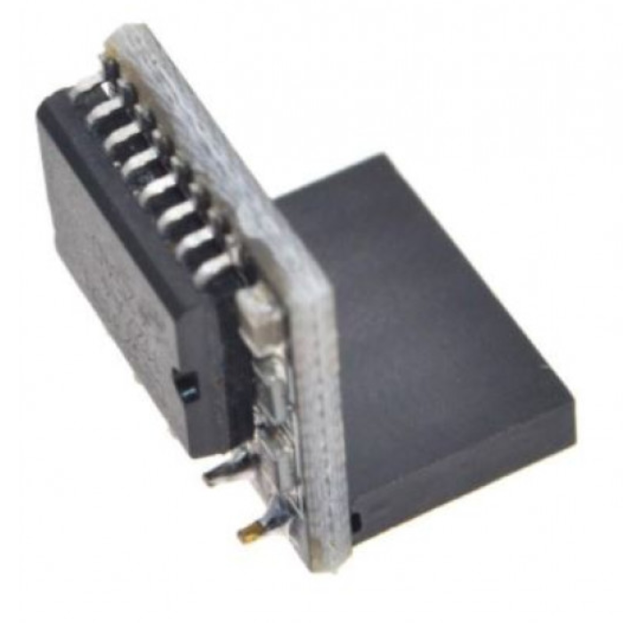
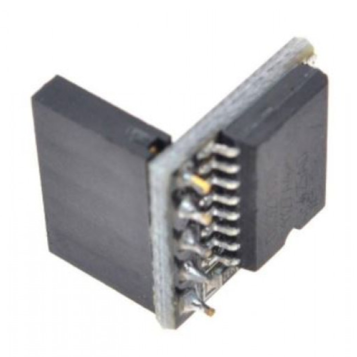
DS3231 Real Time Clock Module for Raspberry Pi (Without Battery)
The DS3231 Real-Time Clock (RTC) Module keeps accurate time for your Raspberry Pi and also works with Arduino. It tracks seconds, minutes, hours, day, date, month, and year, accurate up to the year 2100. The module adjusts to work with 3.3V or 5V, so it’s safe to use with Raspberry Pi. It has two alarms, a 1Hz and 32.768kHz output, and uses a fast I2C connection for easy setup. This low-power module also has a battery backup option (battery not included) to keep time when the main power is off.
₹191,40
MRP. ₹348,60
Incl. GST (No Hidden Charges)
Incl. GST (No Hidden Charges)


DS3231 Real Time Clock Module for Raspberry Pi (Without Battery)
DS3231 Real Time Clock Module for Raspberry Pi (Without Battery) The DS3231 Real-Time Clock (RTC) Module keeps accurate time for your Raspberry Pi and also works with Arduino. It tracks …
As low as
₹191,40
₹191,40
MRP. ₹348,60
Incl. GST (No Hidden Charges)
DTMF Decoder - GL
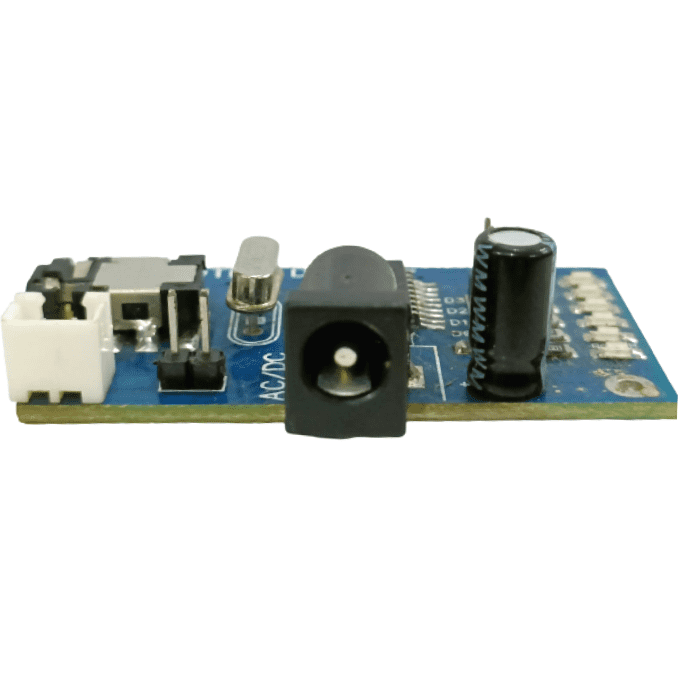
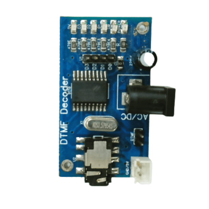
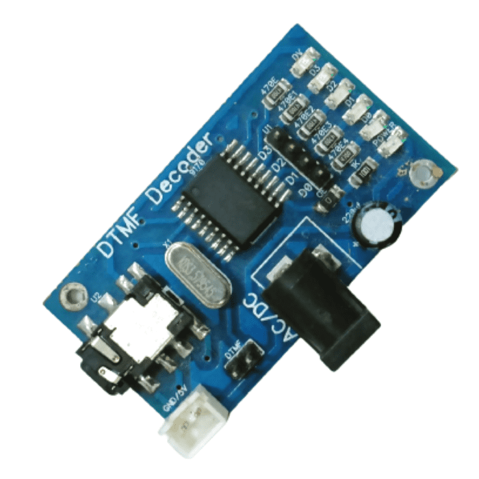
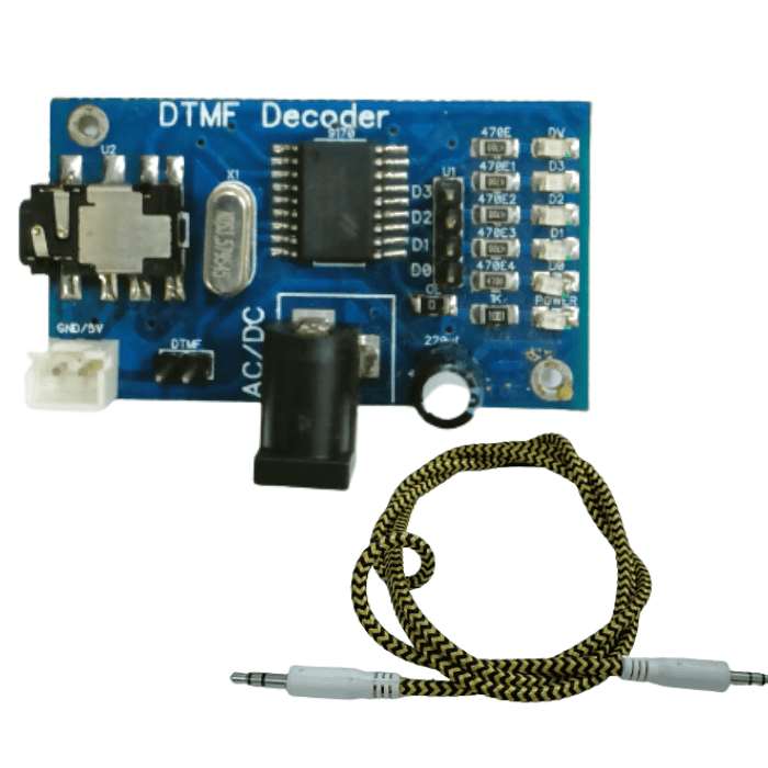
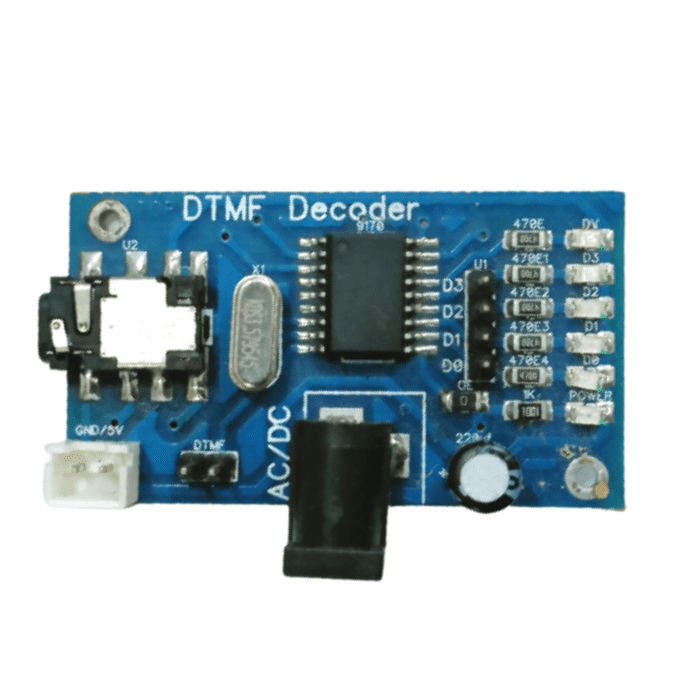
DTMF Decoder - GL
Decodes DTMF audio signal to 4 bit binary TTL level output with LED indication. It also indicates outputs with LED. Can be used directly with microcontrollers to develop various DTMF related applications like remote monitoring, remote control, Caller ID, Auto Dialer, Remote Triggering etc.
read more :
DTMF DECODER: MADE IN INDIA
Applications:
Remote Control systems.
Caller ID applications.
FM receiver-based remote control.
Remote control using a Mobile phone.
₹194,72
Incl. GST (No Hidden Charges)
Out of Stock
MRP. ₹301,00
Incl. GST (No Hidden Charges)
DTMF Decoder - GL
DTMF Decoder - GL Decodes DTMF audio signal to 4 bit binary TTL level output with LED indication. It also indicates outputs with LED. Can be used directly with microcontrollers …
As low as
₹194,72
₹194,72
MRP. ₹301,00
Incl. GST (No Hidden Charges)
Out of Stock
Dual 1-of-4 Line Data Selecto…
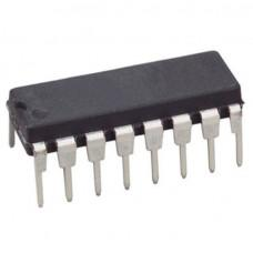
Dual 1-of-4 Line Data Selector/Multiplexer IC - 74HC153
The
74HC Series
74HC153 IC's data selectors/multiplexers contains inverters and drivers to supply fully complementary, on-chip, binary decoding data selection to the AND-OR-invert gates. Separate strobe inputs are provided for each of the two four-line sections.
The 74HC153 features independent enable inputs (n
E
) and common data select inputs (S0 and S1). For each multiplexer, the select inputs select one of the four binary inputs and routes it to the multiplexer output (nY). A HIGH on
E
forces the corresponding multiplexer outputs LOW. Inputs include clamp diodes
Pinout:
Pinout Of 74HC153 IC
₹27,82
MRP. ₹54,60
Incl. GST (No Hidden Charges)
Incl. GST (No Hidden Charges)

Dual 1-of-4 Line Data Selector/Multiplexer IC - 74HC153
Dual 1-of-4 Line Data Selector/Multiplexer IC - 74HC153 The 74HC Series 74HC153 IC's data selectors/multiplexers contains inverters and drivers to supply fully complementary, on-chip, binary decoding data selection to the …
As low as
₹27,82
₹27,82
MRP. ₹54,60
Incl. GST (No Hidden Charges)
Dual 2-to-4 line Decoder/Demu…
Dual 2-to-4 line Decoder/Demultiplexer IC - 74HC139
The
74HC Series
74HC139 comprises two separate two-line-to-four-line decoders in a single package. The active-low enable input can be used as a data line in demultiplexing applications. All of these decoders/demultiplexers feature fully buffered inputs, presenting only one normalized load to its driving circuit. All inputs are clamped with high-performance Schottky diodes to suppress line-ringing and simplify system design.
These Schottky-clamped circuits are designed to be used in high-performance memory-decoding or data-routing applications, requiring very short propagation delay times. In high-performance memory systems, these decoders can be used to minimize the effects of system decoding. When used with high-speed memories, the delay times of these decoders are usually less than the typical access time of the memory. This means that the effective system delay introduced by the decoder is negligible.
Pinout:
Pinout Of 74HC139 IC
Symbol
Pin
Description
1E, 2E
1, 15
enable input (active LOW)
1A0, 1A1
2, 3
address input
1Y0, 1Y1, 1Y2, 1Y3
4, 5, 6, 7
output (active LOW)
GND
8
ground (0 V)
2Y0, 2Y1, 2Y2, 2Y3
12, 11, 10, 9
output (active LOW)
2A0, 2A1
14, 13
address input
VCC
16
positive supply voltage
Also check
4 Bit D-Latch 74LS75 IC
. It's a small, 16-pin integrated circuit (IC) chip that stores 4 bits of digital data. It's commonly used in digital circuits for data storage, timing control, and logic functions.
₹33,38
MRP. ₹61,60
Incl. GST (No Hidden Charges)
Incl. GST (No Hidden Charges)
Dual 2-to-4 line Decoder/Demultiplexer IC - 74HC139
Dual 2-to-4 line Decoder/Demultiplexer IC - 74HC139 The 74HC Series 74HC139 comprises two separate two-line-to-four-line decoders in a single package. The active-low enable input can be used as a data …
As low as
₹33,38
₹33,38
MRP. ₹61,60
Incl. GST (No Hidden Charges)
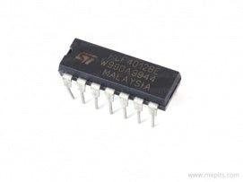
Dual 4 Input AND Gate IC - CD…
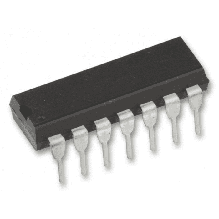
Dual 4 Input AND Gate IC - CD4082
CD4082 belongs to the CD4XXX IC series. This CD4082 is designed as a monolithic Dual 4 Input AND Gate designed by implementing the complementary MOS technology, integrated with P and N-type enhancement mode transistors. The CD4082 IC operates at a wide range of working voltage and a wide range of working conditions. And directly interfaces with CMOS, NMOS, and TTL. The output of the IC always comes in TTL which makes it quite easy to function with other TTL devices and microcontrollers.
The
CD4x Series
CD4082 offers features such as ESD barring and high noise immunity. Each output is protected against static damage by using clamping diodes. CD4081 Operates at a supply voltage of range between 3V to 15V. This IC is designed for operation over the full military temperature range of 0°C to 70°C. The IC CD4082 comes as smaller in size and offers much faster speed which makes it highly reliable in every kind of device. CD4082 IC can be soldered directly to the circuit board or easily mounted on a 14-pin IC base.
The CD4082 is manufactured in 14-lead hermetic dual-in-line ceramic packages (F3A suffix), 14-lead dual-in-line plastic packages (E suffix), 14-lead small-outline packages (M, MT, M96, and NSR suffixes), and 14-lead thin shrink small-outline packages (PW and PWR suffixes).
The AND gate is designed as a basic digital logic gate that implements logical conjunction. An AND gate operates on logical multiplication rules. If all the inputs to the AND gate are HIGH, then the output will be high. If none or not all inputs to the AND gate are HIGH, results in LOW output.
check out :
Dual 4 Input NAND Gate IC - CD4012
Pinout:
Pinout Of CD4082 IC
Application:
Measurement of frequency
Enable gate and Inhibit gate
₹25,59
MRP. ₹40,60
Incl. GST (No Hidden Charges)
Incl. GST (No Hidden Charges)
Dual 4 Input AND Gate IC - CD4082
Dual 4 Input AND Gate IC - CD4082 CD4082 belongs to the CD4XXX IC series. This CD4082 is designed as a monolithic Dual 4 Input AND Gate designed by implementing …
As low as
₹25,59
₹25,59
MRP. ₹40,60
Incl. GST (No Hidden Charges)
Dual 4 Input NAND Gate IC - C…
Dual 4 Input NAND Gate IC - CD4012
The
CD4x Series
CD4012 belongs to the CD4000 IC series. This CD4012 was designed as a monolithic 4-input NAND gate IC designed by implementing the complementary MOS technology, integrated with P and N-type enhancement mode transistors. As a result, provide a symmetrical circuit with output swings essentially equal to the supply voltage. CD4012 is manufactured in a 14-lead dual-in-line plastic or ceramic package and plastic micro package. The CD4012 IC operates at a wide range of working voltage, and a wide range of working conditions. And directly interfaces with CMOS, NMOS, and TTL. The output of the IC always comes in TTL which makes it quite easy to function with other TTL devices and microcontrollers.
Moreover, CD4012 features ESD barring and high noise immunity. Each output is protected against static damage by using clamping diodes. CD4012 Operates at a supply voltage of range between 3V to 20V. This IC is designed for operation over the full military temperature range of 0°C to 70°C. CD4012 Dual 4 Input NAND Gate IC feature a Propagation Delay Time of Max 250ns and Power Dissipation of 250mW.
NAND gate is defined as a digital logic gate most commonly used in DLD applications. It is also sometimes referred to as a universal logic gate and used to implement any logic gate or expression in existence. In case, if any one of the inputs to the NAND gate switch to high, the output of the gate will always be logical low. On the other hand, a NAND gate yields a logical high only when all of its inputs are set to LOW.
check out :
Dual 4 Input AND Gate IC - CD4082
Pinout:
Pinout of CD4012 IC
Application
Automotive
Alarm system
Data terminals
Industrial controls
Instrumentation
Remote metering
Medical Electronics
Computers
₹15,58
MRP. ₹35,00
Incl. GST (No Hidden Charges)
Incl. GST (No Hidden Charges)
Dual 4 Input NAND Gate IC - CD4012
Dual 4 Input NAND Gate IC - CD4012 The CD4x Series CD4012 belongs to the CD4000 IC series. This CD4012 was designed as a monolithic 4-input NAND gate IC designed …
As low as
₹15,58
₹15,58
MRP. ₹35,00
Incl. GST (No Hidden Charges)
